Over-fueling prevention valve

a technology of fuel tank and valve body, which is applied in the direction of functional valve types, fuel injecting pumps, machines/engines, etc., can solve the problems of partially blocked or blocked ventilation passages of canisters, and achieve the effect of increasing the internal pressure of the fuel tank

Inactive Publication Date: 2005-11-01
NIFCO INC
View PDF13 Cites 30 Cited by
  • Summary
  • Abstract
  • Description
  • Claims
  • Application Information

AI Technical Summary

Benefits of technology

[0014]With the above-mentioned configuration, when the fuel level inside the fuel tank reaches the first inlet, i.e. the first level, upon fueling, the fuel enters the first chamber. However, at this stage, the fuel does not enter the second chamber from the second inlet, so that only the first float rises to block the first communicating port. Accordingly, the fuel tank communicates with the ventilation passage only through the second communicating port of the second chamber, thereby increasing the internal pressure of the fuel tank. Thus, the fuel level inside the fuel tube rises, so that the sensor at the fuel nozzle can detect the fill-up.
[0015]Once the fueling through the fuel nozzle is stopped due to the detection, the internal pressure of the fuel tank decreases by ventilation through the second communicating port of the second chamber. As a result, the fuel level inside the fuel tube decreases, so that the sensor at the fuel nozzle terminates the detection of the fill-up.
[0016]When the fuel is added and the fuel level inside the fuel tank reaches the second inlet referred as the second level, which is a level higher than the first level and a limit for the additional fueling, the fuel enters the second chamber. Accordingly, the second float rises to block the second communicating port. Thus, the fuel tank no longer communicates with the ventilation passage, thereby increasing the internal pressure of the fuel tank. The fuel level inside the fuel tube rises again, so that the sensor at the fuel nozzle can detect the fill-up again.

Problems solved by technology

If this happens, the ventilation passage of the canister is blocked or partially blocked to increase the internal pressure of the fuel tank.

Method used


Image

  • Over-fueling prevention valve
  • Over-fueling prevention valve
  • Over-fueling prevention valve

Examples


Embodiment Construction

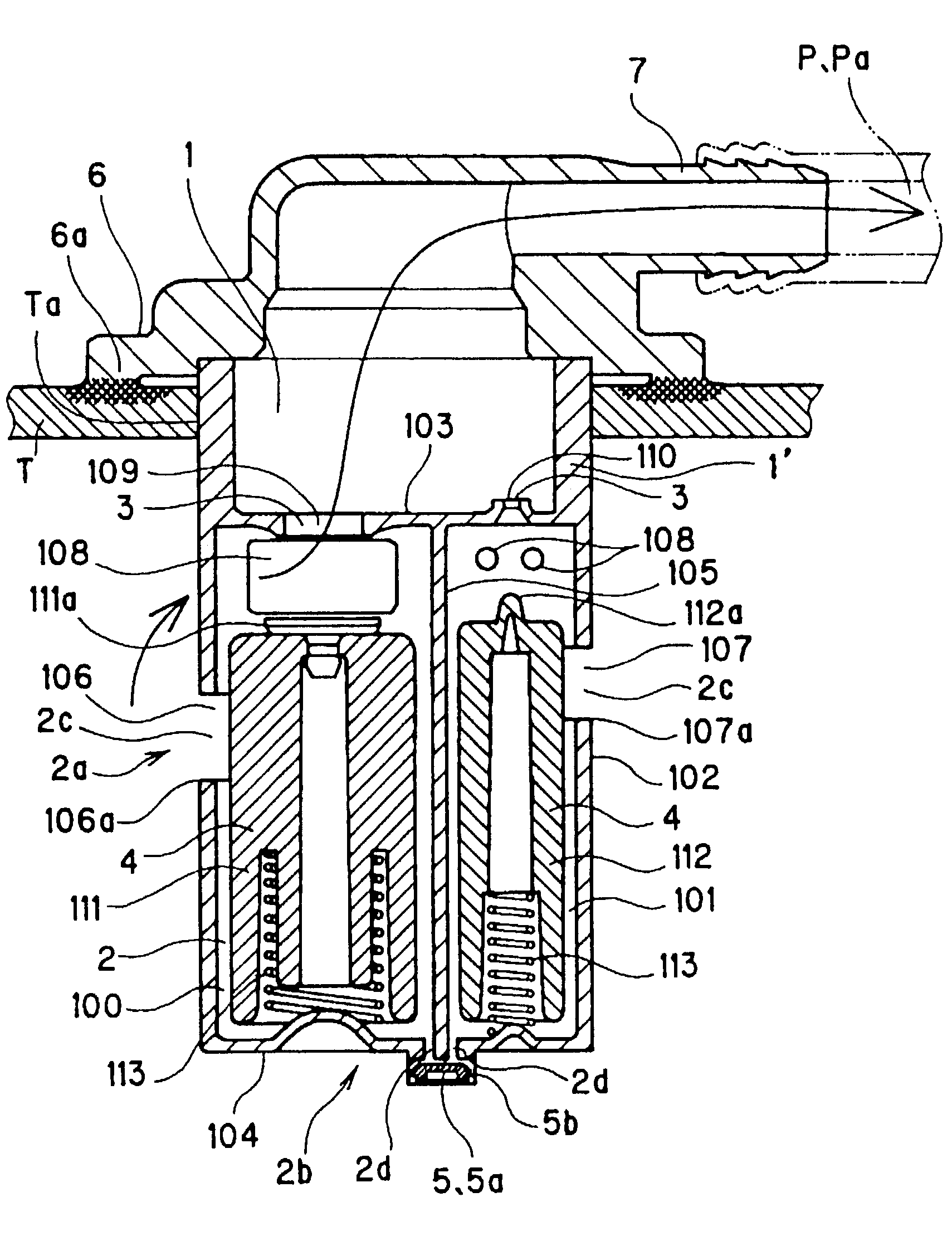
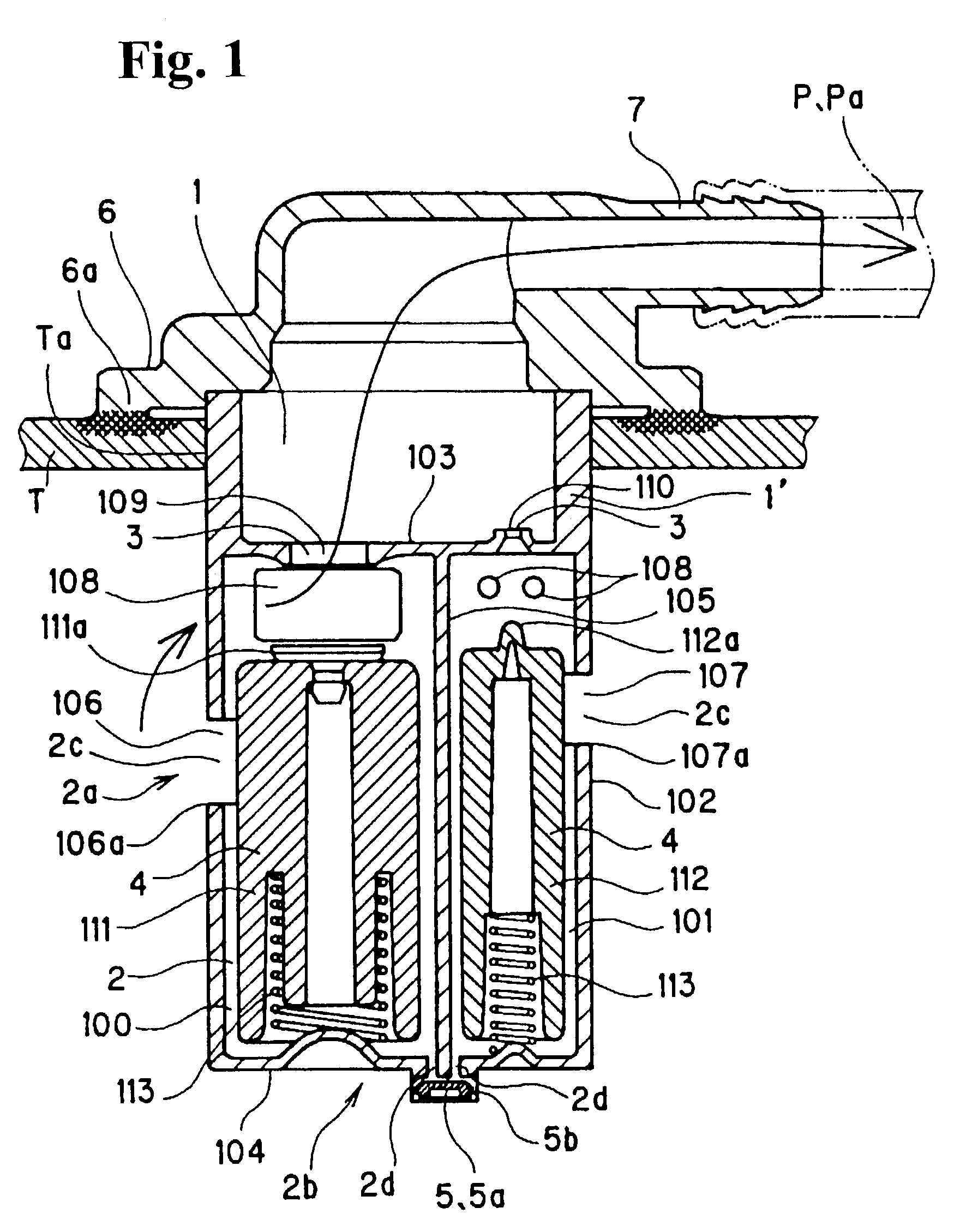
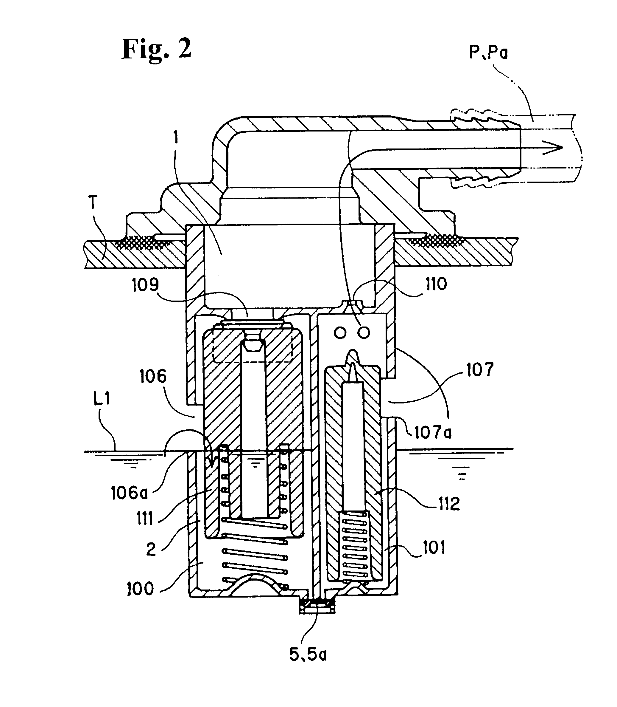
[0041]Hereunder, embodiments of the present invention will be explained with reference to the accompanying drawings.

[0042]In a valve according to the present invention, when a fuel level inside a fuel tank T reaches a predetermined level (hereinafter referred as the first level L1) upon fueling, ventilation to a ventilation passage P of the canister is blocked or reduced, and an internal pressure of the fuel tank T is raised. Accordingly, a fuel level inside a fuel tube is raised by the increase in the internal pressure of the fuel tank T, so that a sensor at a fuel nozzle (also referred as a fuel gun) detects fill-up, thereby preventing over-fueling.

[0043]Also, in the valve of the present invention, when the sensor at the fueling nozzle detects the fill-up, the fueling nozzle automatically stops fueling. Then, when additional fuel, which is allowed due to a decrease in the internal pressure of the fuel tank T, is poured generally through operating the fueling nozzle manually, the f...


PUM


Abstract

A fuel valve includes an upper chamber communicating with a ventilation passage of a canister; a lower chamber to be disposed inside a fuel tank; a communicating port between the upper chamber and the lower chamber; and a float member disposed in the lower chamber for blocking the communicating port when fuel flows into the lower chamber. The lower chamber includes a one-way valve formed at a bottom thereof for allowing the fuel to flow out only through the one-way valve, and a fuel inlet formed in a side wall of the lower chamber. When a fuel level inside the fuel tank reaches the main fuel inlet, the fuel flows into the lower chamber to raise the float member. As a result, an internal pressure of the fuel tank increases, so that a sensor at a fueling nozzle side can detect that the fuel tank is filled-up.

Description

BACKGROUND OF THE INVENTION AND RELATED ART STATEMENT[0001]The present invention relates to a fuel valve for preventing over-fueling. In the fuel valve, when a fuel level inside a fuel tank reaches a predetermined level upon fueling, a ventilation path of a canister is blocked or partially blocked. As a result, an internal pressure of the fuel tank increases to raise a fuel level inside a fuel tube, so that a sensor at a fueling nozzle can detect the fuel tank is filled.[0002]A conventional fuel valve includes a skirt support portion with an opening lower end disposed inside a fuel tank for covering around a connection portion between the fuel tank and a ventilation path of a canister. When a fluid level inside the fuel tank reaches the opening lower end of the skirt support portion, an internal pressure of the fuel tank increases. As a result, a fuel level inside a fuel tube rises so that a sensor at a fueling nozzle side can detect fill-up, thereby preventing over-fueling. (For ex...

Claims


Application Information

Patent Timeline
Patent Type & Authority Patents(United States)
IPC IPC(8): B60K15/035B60K15/03F02M25/08B60K15/077F02M37/00F16K24/04
CPCB60K15/03519F02M25/08B60K2015/03576Y10T137/0874Y10T137/3099B60K15/077
Inventor KURIHARA, KAZUMASAKOBAYASHI, YASUTOMO
Owner NIFCO INC
Why Eureka
Try Eureka