Camera built-in type rearview mirror device

Inactive Publication Date: 2005-11-01
MURAKAMI CORP
View PDF23 Cites 156 Cited by
  • Summary
  • Abstract
  • Description
  • Claims
  • Application Information

AI Technical Summary

Problems solved by technology

However with this rearview mirror device, the road surface ranging from downward to a slantingly forward cannot be visually recognized.
When an obstacle exists near this field, there is a possibility of involving this in a front wheel without knowing.
Therefore, the problem that the rigidity of the mirror housing falls, resulting in trembling vibration that is occurred to the mirror, is pointed out.
Moreover, since the position of the lens of the camera main body part is restricted by the transparent cover that closes the opening, the problem that photographing feasible viewing angle is generally narrow, is also pointed out.
Furthermore, since protection against dust and moisture impervious methods are not taken inside of the transparent cover, dirt which invaded in the mirror housing from the circumference of the mirror, etc may adhere to the inside of the transparent cover.
In addition, fogging and dew condensation

Method used


Image

  • Camera built-in type rearview mirror device
  • Camera built-in type rearview mirror device
  • Camera built-in type rearview mirror device

Examples


Embodiment Construction

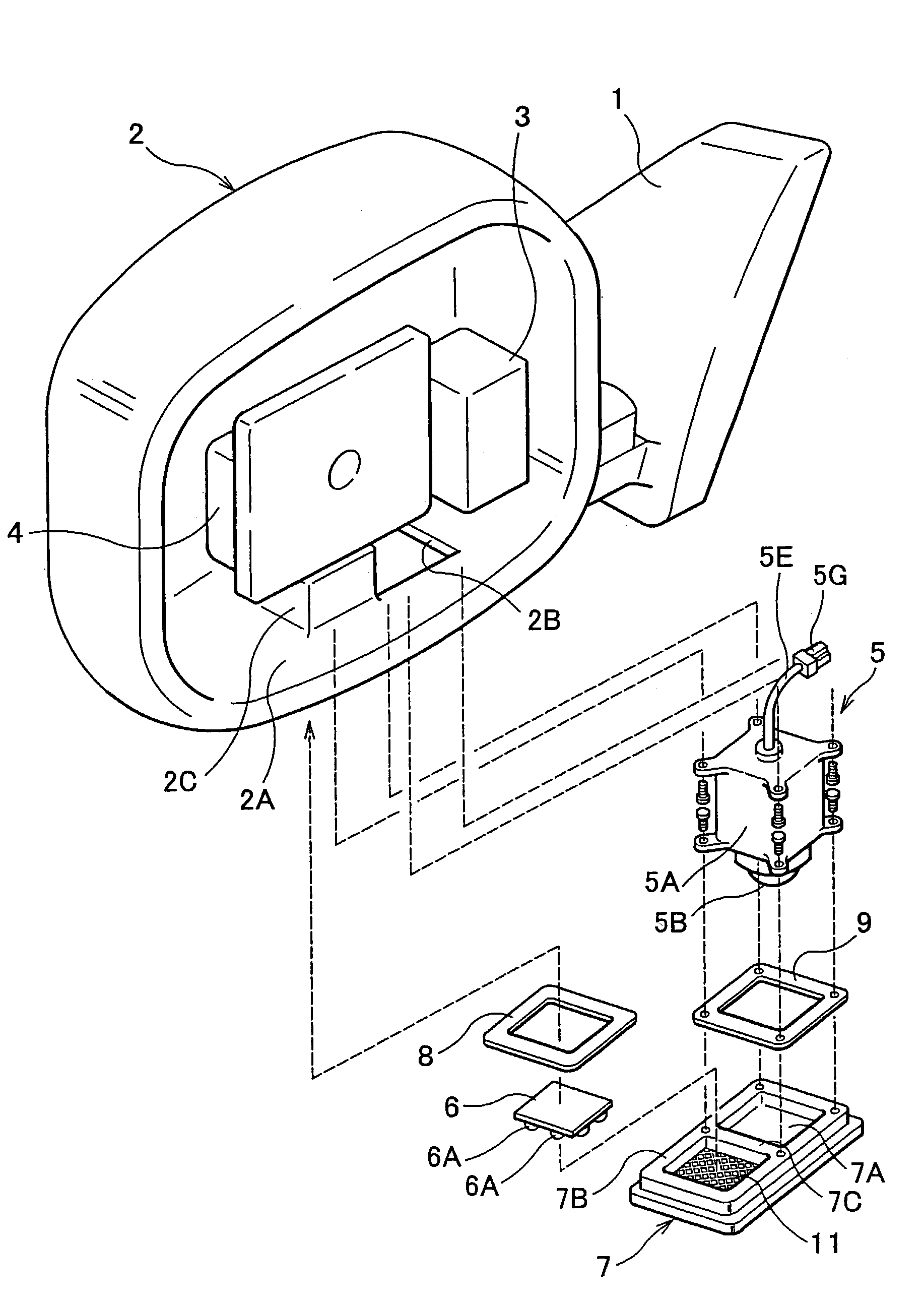
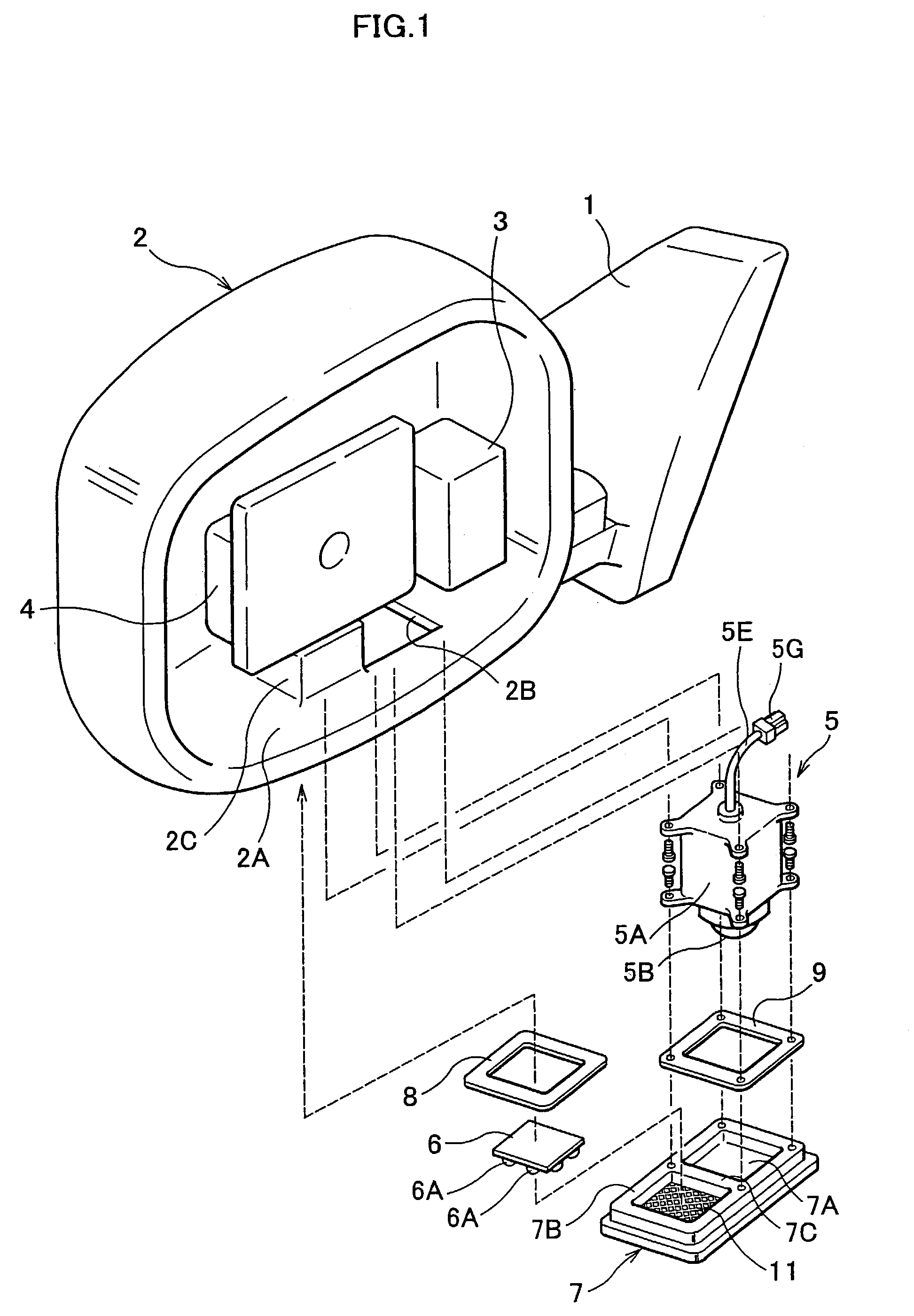
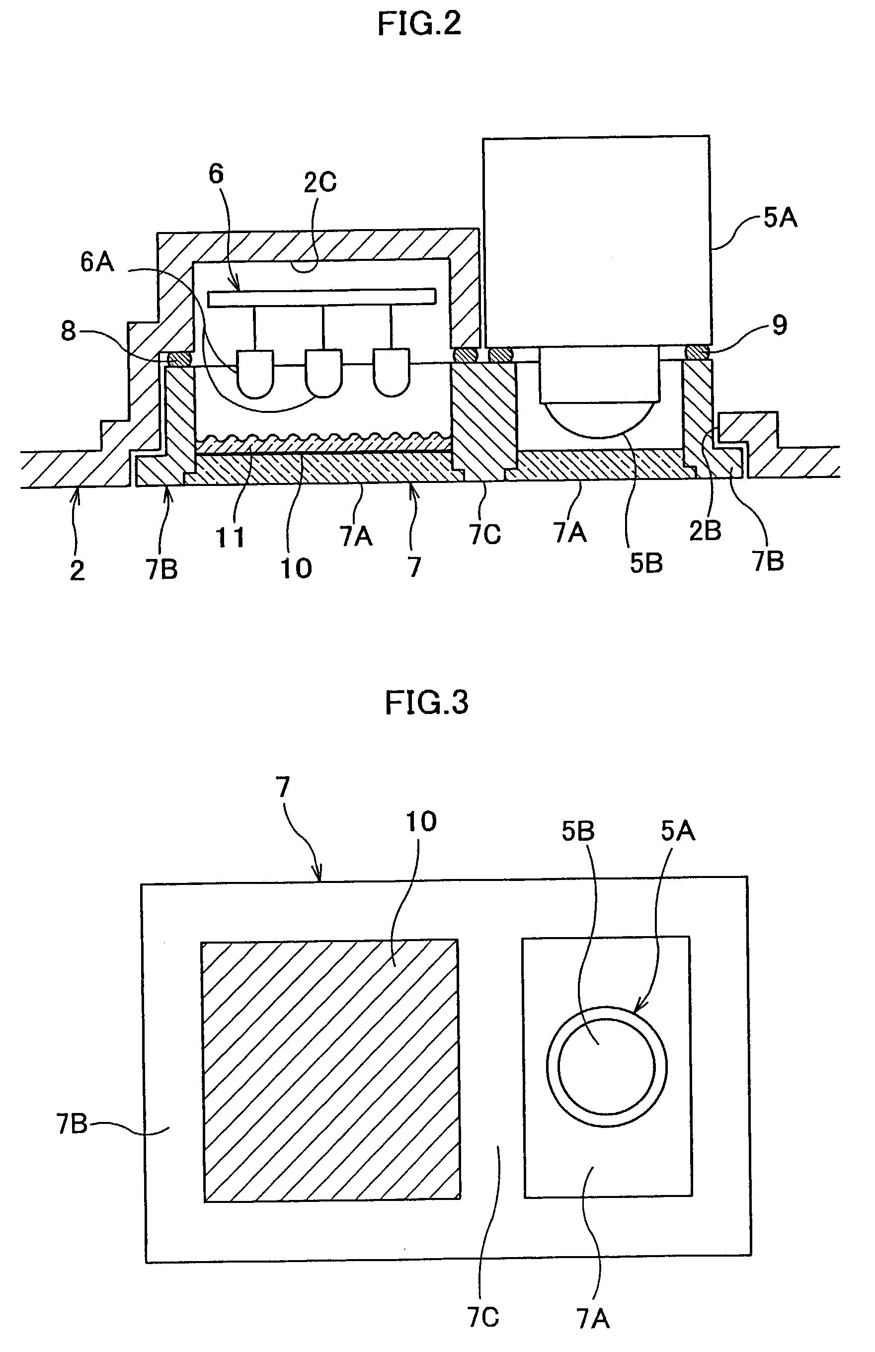
[0015]Hereafter, the embodiment of the camera built-in type rearview mirror device according to this invention will be explained in conjunction with the drawings. In the drawing to refer to, FIG. 1 is a perspective view showing a substantial structure of the inside when removing a mirror from the camera built-in type rearview mirror device according to one mode of the embodiment, FIG. 2 is a partially enlarged sectional view of the photographing window formed in the lower part of the mirror housing shown in FIG. 1 and near the concave part, and FIG. 3 is a front view of the transparent cover shown in FIG. 2 viewed from the lower part of the mirror housing.

[0016]A camera built-in type rearview mirror device of one embodiment is constituted in such a way that as shown in FIG. 1, mirror housing 2 is rotated to mirror base 1 about a substantially perpendicular fulcrum axis by the drive of a motor (not shown) of electric retractable mirror 3, wherein the mirror base 1 is used by being fi...


PUM


Abstract

To provide a camera built-in type rearview mirror device with illumination, wherein rigidity of the mirror housing can be raised, the camera main body part can photo a clear picture by extensive photographing feasible viewing angle through a transparent cover, and built-in of the camera module is simple. Mirror housing 2 includes concave part 2C formed in an opening manner downwardly which is arranged in the vicinity of photographing window 2B where lens 5B of the camera main body part 5A is faced, and capable of accommodating an illumination light source. For this reason, opening area of the photographing window 2B is decreased. Also, the circumference of the photographing window 2B is reinforced by the cross-sectional box type form of the concave part 2C. Especially a bulge part with circular curved section is formed so that the lens of the camera main body part may rush in, to thereby decrease the opening area of the photographing window further. Then rigidity of the mirror housing 2 is further raised.

Description

FIELD OF THE INVENTION[0001]This invention relates to a rearview mirror device for rearward visual recognition attached to such as door of vehicles for example, more specifically relates to a camera module for downward visual recognition in which the camera module for downward visual recognition is built in.BACKGROUND OF THE INVENTION[0002]Generally, rearview mirror devices for rearward recognition are attached to the right and left door of a vehicle. However with this rearview mirror device, the road surface ranging from downward to a slantingly forward cannot be visually recognized. For this reason, especially in the field of view seen from a driver's seat of a car, the road surface near the front wheel on the side of a passenger seat serves as a dead angle. When an obstacle exists near this field, there is a possibility of involving this in a front wheel without knowing. Then, in order to avoid such a situation, a camera built-in type rearview mirror device including a camera mod...

Claims


Application Information

Patent Timeline
IPC IPC(8): B60R1/00B60R1/12G03B15/00B60R1/06H04N5/225
CPCB60R1/00B60R1/12B60R1/1207B60R11/04B60R2001/1253B60R2300/103B60R2300/106B60R2300/8053
Inventor FUJIKAWA, YOSHIHIROHITOMI, YOSHINORISUZUKI, HISAYAKOBAYASHI, AKIYOSHI
Owner MURAKAMI CORP
Why Eureka
Try Eureka