Cutting machine with environment control arrangement

a cutting machine and environment control technology, applied in the field of cutting machines, can solve the problems of residual particles being considered as one of the air pollutions, affecting the safety of users, and affecting the operation of the cutting machine, so as to avoid air and land pollution

a cutting machine and environment control technology, applied in the field of cutting machines, can solve the problems of residual particles being considered as one of the air pollutions, affecting the safety of users, and affecting the operation of the cutting machine, so as to avoid air and land pollution

US6960124B2Inactive Publication Date: 2005-11-01LEE WY PERON

Image

  • Cutting machine with environment control arrangement
  • Cutting machine with environment control arrangement
  • Cutting machine with environment control arrangement

Examples


Embodiment Construction

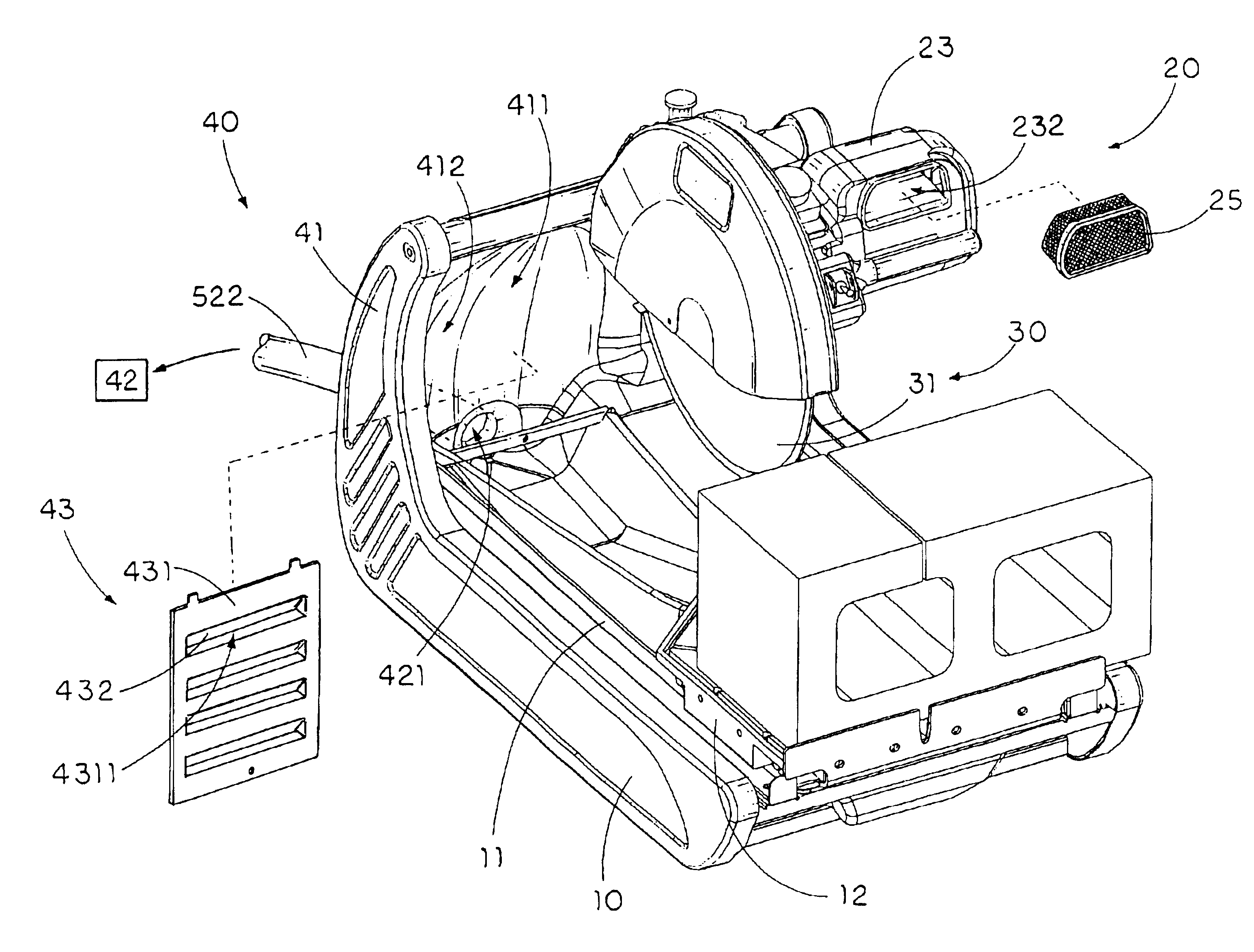
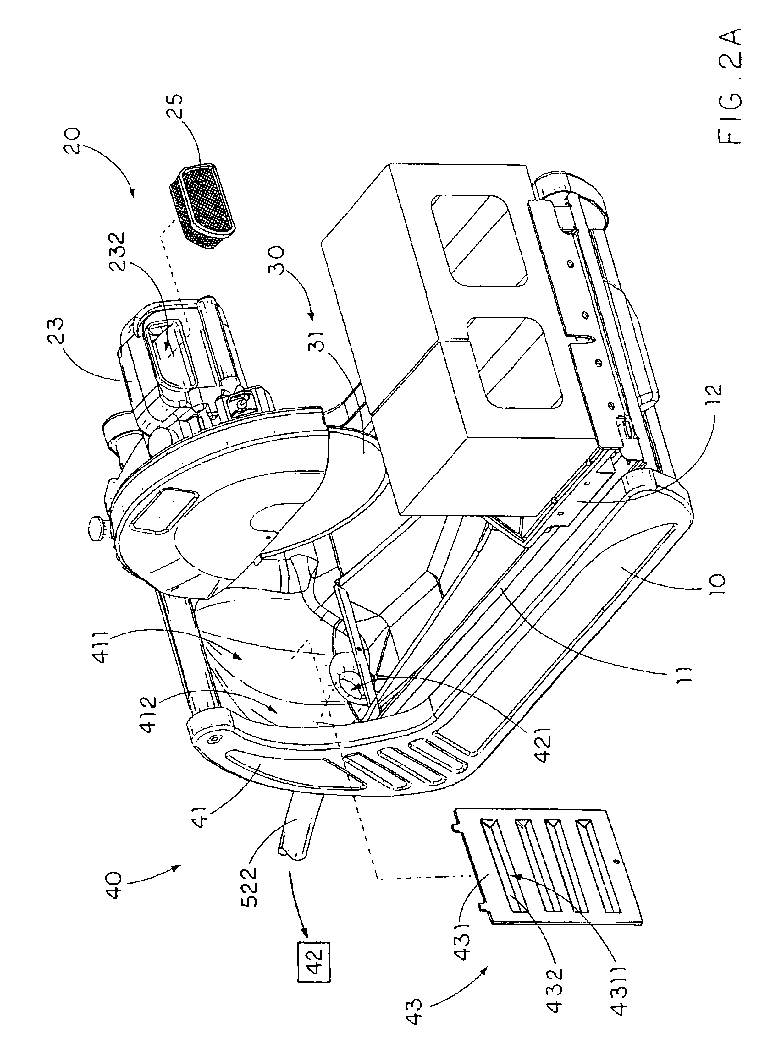
[0032]Referring to FIGS. 2A, 2B and 3 of the drawings, a cutting machine according to a preferred embodiment of the present invention is illustrated, wherein the cutting machine comprises a cutting support frame 10 comprising a bottom collecting tray 11 and a cutting table 12 mounted thereon for supporting a work piece, and a motor assembly 20, which is supported on the bottom collecting tray 11, comprising a driving motor 21 and a driving shaft 211 being driven to be rotated by the driving motor 21.

[0033]The cutting machine further comprises a cutting head arrangement 30 comprising a cutting blade 31 coaxially mounted to the driving shaft 211 at a position overhanging the cutting table 12, wherein the cutting blade 31 has a cutting area 311 defined at an outer circumferential portion thereof when the cutting blade 31 cuts the work piece.

[0034]The cutting table 12 is slidably mounted on the bottom collecting tray 11 wherein the work piece is placed on the cutting table 12 in such a ...


PUM

PropertyMeasurementUnit
areaaaaaaaaaaa
circumferenceaaaaaaaaaa
diameteraaaaaaaaaa

Abstract

A cutting machine includes a bottom collecting tray, a cutting blade overhanging on a cutting table and having a cutting area defined at an outer circumferential portion thereof when the cutting blade cuts the work piece, and an environment control arrangement. The environment control arrangement includes an end collecting tray, which is upwardly extended from the bottom collecting tray, having a collecting chamber for collecting residual particles of the work piece while the cutting blade cuts the work piece, wherein the end collecting tray must be upwardly extended to a position above the cutting area of the cutting blade, and a suction source having a sucking inlet provided at a lower portion of the end collecting tray for collecting the residual particles within the collecting chamber by means of sucking effect.

Description

BACKGROUND OF THE PRESENT INVENTION[0001]1. Field of Invention[0002]The present invention relates to a cutting machine, and more particularly to a cutting machine with an environment control arrangement which is capable of effectively collecting the residual particles during the cutting process so as to reduce the pollution of spitting out of the residual particles and to prevent the motor from sucking the residual particles thereinto.[0003]2. Description of Related Arts[0004]Conventional cutting machines are widely used in various industries for provision of rapid and high quality cutting of such construction and manufacturing materials as granite, marble, slate, pave, brick, ceramics, and masonry. A conventional cutting machine generally comprises a supporting frame, a cutting platform slidably mounted on the supporting frame, and a cutter head which is movably overhung on top of the cutting platform and comprises a cutting blade driven by a motor to cut a work piece laid and fixe...

Claims


Application Information

Patent Timeline
01 Nov 2005
Publication
US6960124B2
IPC
B23D59/00; B23Q11/00; B28D7/00; B28D7/02; B28D1/04; B28D1/02; A47L5/36; A47L9/10
CPC
A47L5/365; A47L9/102; B23D59/006; B23Q11/0046; B23Q11/006; B28D1/044; B28D1/047; B28D7/02
Inventors
LEE, WY PERON