Therapeutic back exercise machine

a back exercise machine and back exercise technology, applied in the field of therapeutic back exercise machines, can solve the problems of ineffectiveness, time-consuming and expensive process, and over two hours of machine use, and achieve the effect of saving a considerable amount of time and money

Inactive Publication Date: 2005-11-01
FENKELL RANDALL
View PDF39 Cites 10 Cited by
  • Summary
  • Abstract
  • Description
  • Claims
  • Application Information

AI Technical Summary

Benefits of technology

[0009]Accordingly, it is an object of the present invention to provide a back exercise table of the type disclosed in the '691 patent wherein all of the advantages of the table are maintained but the disadvantages described above are eliminated.
[0010]It is a more specific object of the present invention to provide an improved structure of the back exercise table disclosed in the '691 patent which eliminates the need for Heliarc welding.
[0011]It is another object of the present invention to provide an improvement over the back exercise table disclosed in the '691 patent in the form of a simpler method and apparatus for the effecting reciprocating motion that produces the alternating compression and traction forces.

Problems solved by technology

This necessitated Heliarc welding, an expensive, time-consuming process that took over two hours per machine because of the sixty-four locations to be welded.
This proved to be not very effective and was, in fact, ultimately replaced with two straps that went over the feet and around posts attached to the motor box.

Method used


Image

  • Therapeutic back exercise machine
  • Therapeutic back exercise machine
  • Therapeutic back exercise machine

Examples


Embodiment Construction

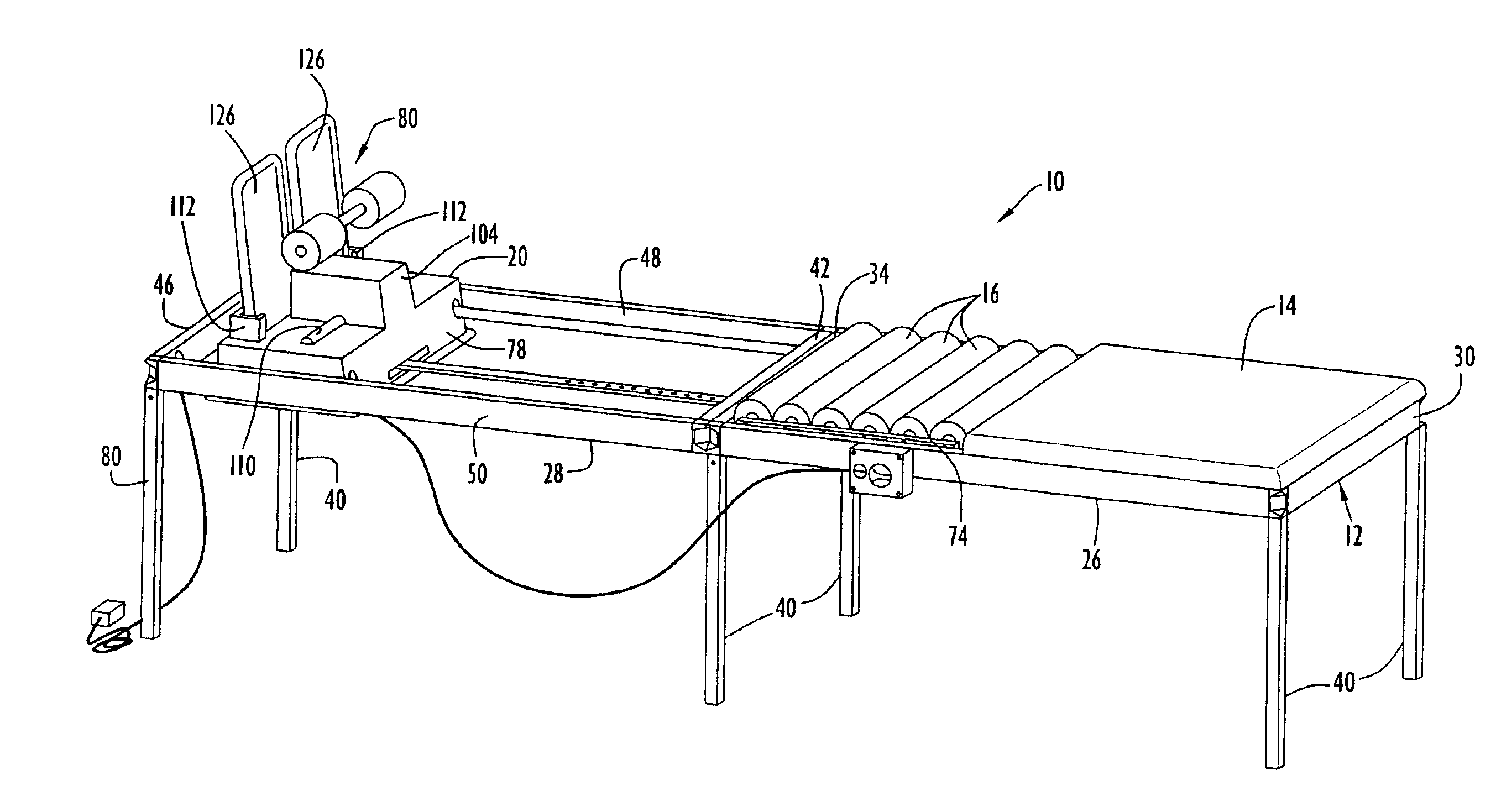
[0031]Referring to the accompanying drawings in greater detail, a therapeutic treatment machine 10 according to the present invention includes a rectangular table frame 12 supporting an upper body pad 14 located toward the head end of the table, a series of six freely rotatable massage rollers 16 located toward the middle of the table and a motor driven, longitudinally and selectively reciprocable foot support platform 20 located toward the foot end of the table. Rectangular frame 12 is made of, for instance, aluminum angle or tube, and has a forward or torso-supporting frame section 26 housing the upper body pad 14 and rollers 16, and a rearward or foot-supporting frame section 28 housing the foot support platform 20. Frame sections 26 and 28 are rectangular and of similar size and shape. Forward section 26 has a forward or head end member 30 and a rearward end 34 extending transversely between opposite longitudinally extending side members. Table legs 40 support the machine at a c...


PUM


Abstract

A therapeutic treatment machine alternatingly applies compression and traction to a patient. A frame includes: a platform having an upper body support pad with controllable resistance to forward and backward displacement; rollers supporting the lower back, buttocks and thighs; and a motor-driven foot support displaceable forward and backward predetermined distances and speeds. Tubular frame members fit over and adhesively engage arms projecting orthogonally from a corner section. Legs telescopically receive leg support members extending orthogonally from the arms. Compression and traction are each forcefully effected by motor rotation converted to longitudinal reciprocation of a linkage that drives the foot support. The patient's feet are held in place against footplates by clamps supported on a T-bar cross member having a stem extending forwardly through a longitudinal slot in the footplates. A threaded bolt extends through the slot to engage the platform at selectable locations to secure the T-bar to the footplates.

Description

CROSS REFERENCE TO RELATED APPLICATIONS[0001]This application claims priority from U.S. Provisional Patent Application Ser. No. 60 / 472,112, filed May 21, 2003, and entitled “Exercise Machine”. The disclosure of that patent application is incorporated herein by reference in its entirety. In addition, the present invention is an improvement over the “Therapeutic Treatment Machine” disclosed in my prior U.S. Pat. No. 5,505,691, issued Apr. 9, 1996 (referred to herein as the '691 patent”), the entire disclosure from which is incorporated herein by reference.BACKGROUND OF THE INVENTION[0002]1. Technical Field[0003]The present invention relates to methods and apparatus for therapeutically treating the human body and, more particularly, to a method and apparatus for relieving discomfort and pain in the back, spine and neck of a human patient.[0004]2. Discussion of Related Art[0005]The essence of the invention disclosed in my prior in my prior U.S. Pat. No. 5,505,691 (referred to herein as ...

Claims


Application Information

Patent Timeline
Patent Type & Authority Patents(United States)
IPC IPC(8): A61H15/00A61HA61H1/00A61H1/02A61H5/00A61H7/00A61H19/00
CPCA61H1/0218A61H1/0222A61H1/0292A61H2001/0233A61H2201/1642A61H2203/0456
Inventor FENKEL, RANDALL
Owner FENKELL RANDALL
Why Eureka
Try Eureka