

Brace for osteoarthritic knee
a knee joint and bone brace technology, applied in the field of bone brace for osteoarthritis of the knee joint, can solve the problems of cartilage of the knee joint becoming worn, pain becoming constant, and reducing movemen
- Summary
- Abstract
- Description
- Claims
- Application Information
AI Technical Summary
Benefits of technology
Problems solved by technology
Method used
Image

Examples
Embodiment Construction
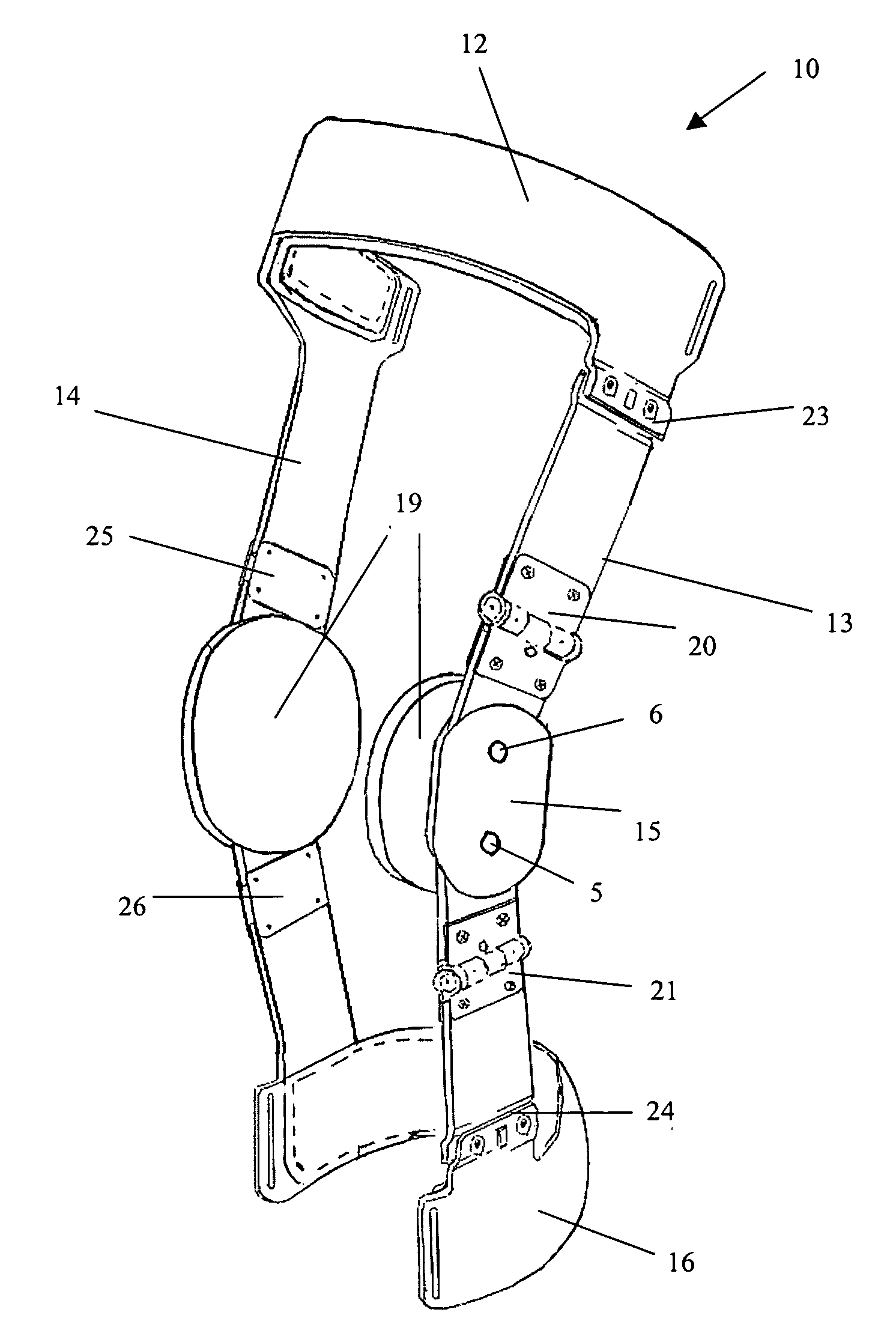
[0026]The present invention proposes to provide a knee brace, in particular for arthritic or osteoarthritic knees, which can eliminate or significantly reduce the drawbacks described above.
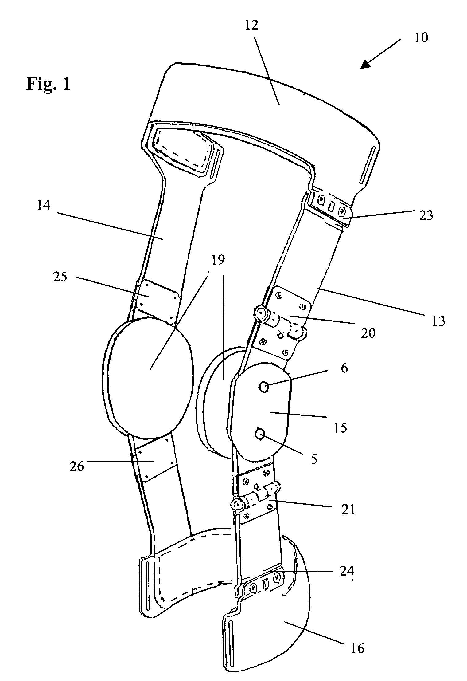
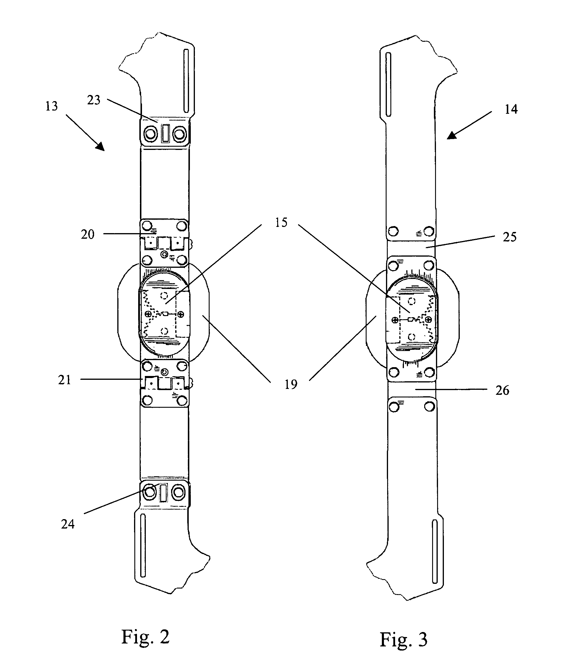
[0027]The present invention also proposes to provide a brace which is easy to adjust, even by the user, and which thanks to the presence of side uprights adaptable to the structure of the limb and the knee joint during flexion provides an appropriately controlled force at the knee, perpendicular to the axis of the leg, in such a way to exert a thrust force which alters the contact between the opposite condyles of the knee bone, reducing the pressure exerted on these condyles and limiting the pain.
[0028]This is achieved by means of a knee brace with the features described in the main claim and which can be applied in particular in osteoarthritic disorders of the knee.
[0029]The dependent claims describe advantageous forms of embodiment of the invention.
[0030]According to an advantageous form of embo...
PUM
 Abstract
Description
Claims
Application Information