High temperature/high pressure vessel

a high temperature/high pressure vessel technology, applied in the field of high temperature/high pressure vessels, can solve the problems of increasing running costs, difficult to effectively cool portions of the vessel packing, and inability to thin the cylindrical body beyond a certain level, so as to prevent the wetness of piano wire with cooling water, effectively cool the vessel packing, and effectively utilize the internal space of the vessel

Active Publication Date: 2005-11-01
KOBE STEEL LTD
View PDF3 Cites 3 Cited by
  • Summary
  • Abstract
  • Description
  • Claims
  • Application Information

AI Technical Summary

Benefits of technology

[0007]It is an object of the present invention to provide a high temperature/high pressure vessel capable of cooling vessel packings effectively,

Problems solved by technology

However, in point of strength, it is impossible to thin the cylindrical body beyond a certain level.
Therefore, in the prior art 1, particularly in the case of a large-sized high temperature/high pressure vessel, it is difficult to effectively cool portions where vessel packings are disposed.
As a result of the temperature of the vessel packings becoming high, the life thereof becomes short, thus causing an increase of running cost.
Moreover, if the prior art 1 is of a construction wherein piano wire is wet with cooling water, the piano wire rus

Method used


Image

  • High temperature/high pressure vessel
  • High temperature/high pressure vessel
  • High temperature/high pressure vessel

Examples


embodiment 1

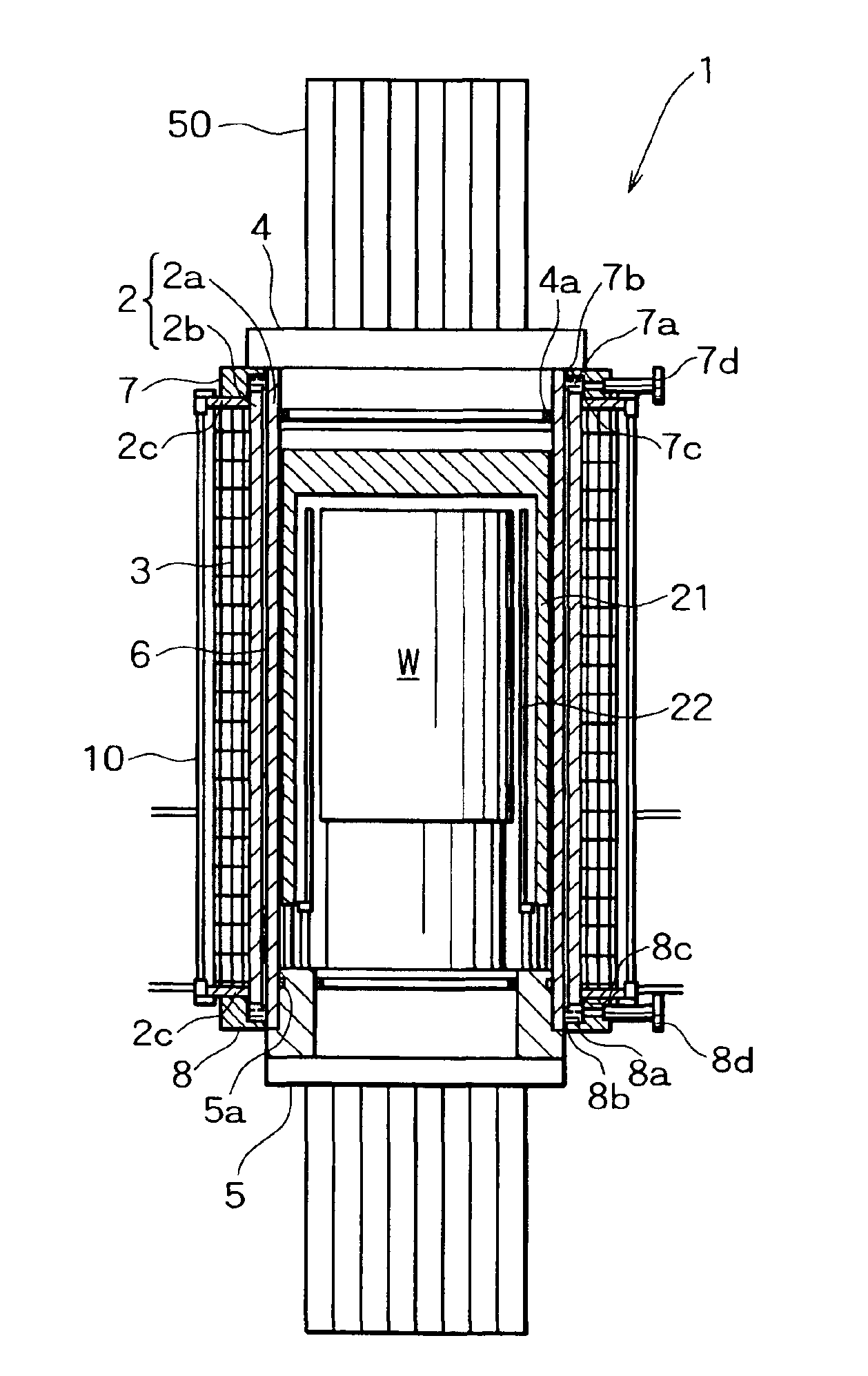
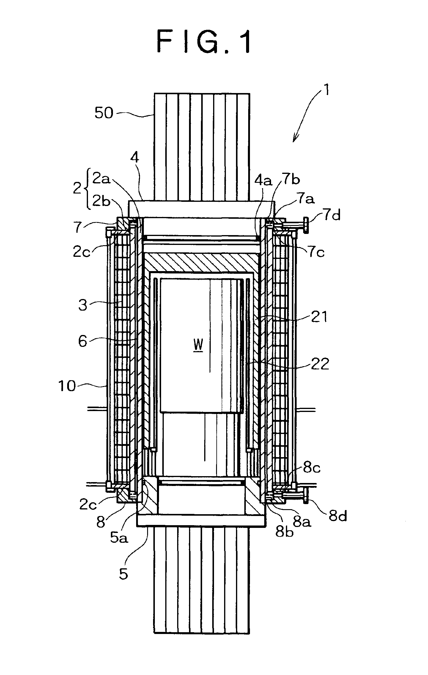
[0044]A high temperature / high pressure vessel according to the present invention will be described hereinunder with reference to the accompanying drawings. FIG. 1 is a vertical sectional view of the high temperature / high pressure vessel as installed within a press frame and FIG. 2 illustrates a part of a cross section of the high temperature / high pressure vessel.

[0045]In those figures, the reference numeral 1 denotes the high temperature / high pressure vessel which is installed within a press frame 50 removably. The high temperature / high pressure vessel 1 is provided with a cylindrical body 2 of a construction to be described later and piano wire 3 wound under a predetermined tension round an outer periphery surface of the cylindrical body2. An upper opening of the cylindrical body 2 is hermetically sealed by fitting therein of an upper lid 4, the upper lid 4 having a high pressure sealing ring 4a as a high pressure packing fitted in a sealing ring groove, while a lower opening of th...

first embodiment

[0069]As in the first embodiment, for deforming the spacers 6 so as to follow the outer periphery profile of the inner cylinder 2a, there also may be adopted a method wherein the outer cylinder 2b is fitted on the spacers 6 fixed to the inner cylinder 2a, thereafter the piano wire 3 is wound round the outer periphery of the outer cylinder 2b, and the spacers 6 are allowed to shrink so as to follow the outer periphery profile of the inner cylinder 2a due to shrinkage of the outer cylinder 2b. According to this method, heating energy for the outer cylinder 2b is not needed and the number of working steps is reduced. Thus, this method is advantageous in point of shortening of the delivery period and energy saving over the foregoing method wherein the outer cylinder 2b is heated.

[0070]Since the high temperature / high pressure vessel 1 of this embodiment 1a is of a construction wherein cooling water flows through cooling water flow paths each formed between adjacent ones of the spacers 6 ...

embodiment 2

[0088]The spacers 6 and the cooling water pipes 9 are brought into close contact with the outer periphery surface of the cylindrical body 2 by being deformed with the piano wire 3 wound thereon. According to this method, heating energy for shrinkage fit is not needed and the number of working steps required is reduced. Thus, this method is superior in point of shortening of the delivery period and energy saving in comparison with the method wherein the outer cylinder is heated for shrinkage fit. In this embodiment 2, for improving the cooling performance, a high heat conductive material is filled between the outer periphery surface of the cylindrical body 2 and the cooling water pipes 9 and also between the cooling water pipes 9 and the spacers 6. As the high heat conductive material there may be used, for example, high heat conductive silicone grease (silicone compound) or silicone rubber with a high heat conductive material incorporated therein.

[0089]An annular cooling water colle...


PUM

PropertyMeasurementUnit
Temperatureaaaaaaaaaa
Pressureaaaaaaaaaa

Abstract

In a high temperature/high pressure vessel for treating a workpiece placed in the interior of the vessel at a high temperature and a high pressure wherein piano wire is wound under tension round an outer periphery of a cylindrical body to apply a compressive residual stress to the cylindrical body and axial openings of the cylindrical body are tightly closed with upper and lower lids so that the lids can be disengaged from the openings, the cylindrical body is constituted as a two-layer cylindrical body comprising an inner cylinder and an outer cylinder which is fitted on the inner cylinder through plural spacers arranged along an outer periphery surface of the inner cylinder, allowing cooling water flow paths to be formed each between adjacent such spacers so as to extend from one end side to an opposite end side of the tow-layer cylindrical body. In this high temperature/high pressure vessel, vessel packings can be cooled effectively, the piano wire is not wet with cooling water, and the internal space of the vessel can be utilized effectively.

Description

BACKGROUND OF THE INVENTION[0001]1. Field of the Invention[0002]The present invention relates to an improvement of a high temperature / high pressure vessel used for an HIP (hot isostatic pressing) apparatus and more particularly to a high temperature / high pressure vessel with piano wire wound under tension round an outer periphery of a cylindrical body of the vessel.[0003]2. Description of the Related Art[0004]For pressure sintering of various powdery materials such as powdered metals and ceramics, for removing internal defects of cast products and sintered products, and for diffusion bonding, an HIP apparatus which utilizes a synergistic effect of a high isotropic pressure and a high temperature within a high pressure vessel is adopted in various industrial fields. The HIP apparatus is composed of a high temperature / high pressure vessel (with a heat insulating layer and a heater disposed in the interior thereof) into which a high pressure gas is sealed, an upper lid and a lower lid ...

Claims


Application Information

Patent Timeline
IPC IPC(8): C21D9/00F27B17/00
CPCB30B11/002C21D9/00C21D9/0006C21D2241/01
Inventor YONEDA, MAKOTONAKAI, TOMOMITSUKOFUNE, SHIGEONARUKAWA, YUTAKAKANDA, TAKESHINISHIMOTO, TAKEO
Owner KOBE STEEL LTD
Why Eureka
Try Eureka