Measuring assembly

Inactive Publication Date: 2005-11-01
LEN LEONARD F
View PDF1 Cites 0 Cited by
  • Summary
  • Abstract
  • Description
  • Claims
  • Application Information

AI Technical Summary

Benefits of technology

[0007]A measuring assembly and machining assembly allowing for easy access and maintenance of the measuring assembly. Furthermore, the measuring assembly may be positioned in the tool assembly including portions which allow for easy access and maintenance of the measuring assembly. Generally, the measuring assembly is disposed within a bushin

Problems solved by technology

Therefore, increased longevity and reduced maintenance of the measur

Method used


Image

  • Measuring assembly
  • Measuring assembly
  • Measuring assembly

Examples


Example

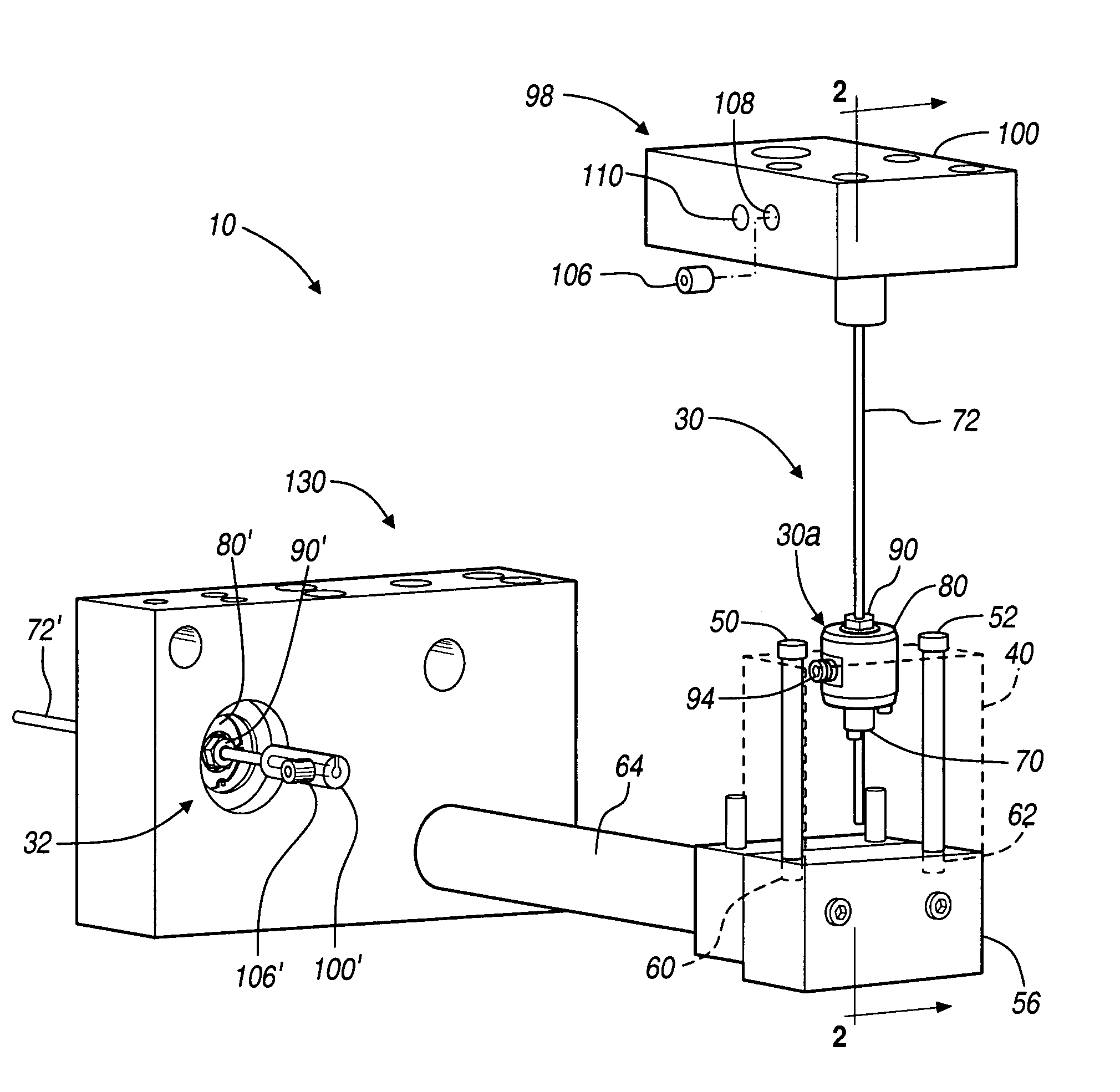
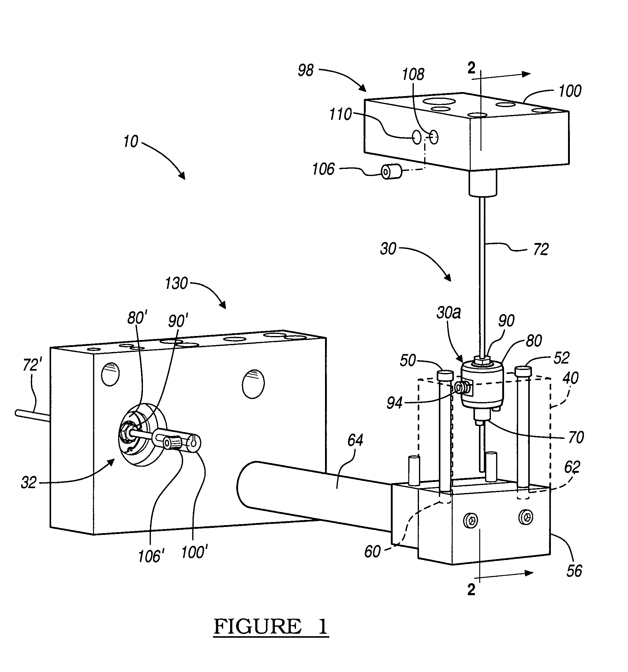
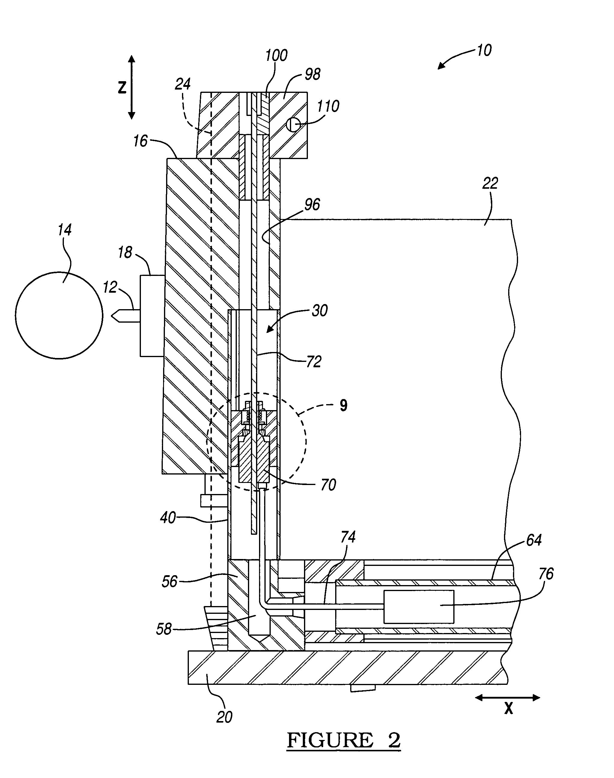
[0023]The following description of various embodiments is merely exemplary in nature and is in no way intended to limit the invention, its application, or uses. For example, although the following description relates specifically to a two-axis assembly, it will be understood that any appropriate number of axes may be measured. Moreover, the invention may be used in conjunction with any appropriate assembly, such as a lathe, mill, or machine.

[0024]With reference to FIGS. 1 and 2 a tooling assembly 10 can be used to cut, turn, or perform other appropriate work with a tool 12 to a member or material 14. The tool 12 extends from a tooling or cutting head 16 and may be held with a chuck 18 or other appropriate portion. The machining tool 10 is generally provided to move along a first linear way 20. It will be understand that any appropriate mechanism may be used to allow translation of the assembly 10. The first linear way 20 allows the entire machining assembly 10 to move along a first ...


PUM


Abstract

A measuring assembly and machining assembly allowing for easy access and maintenance of the measuring assembly. The measuring assembly is disposed within a bushing to allow for easy removal of the measuring assembly. Furthermore, the machining assembly allows for access and maintenance of the measuring assembly with little or no disassembly of the machining assembly. Therefore, increased longevity and reduced maintenance of the measuring assembly is required during operation of the machining assembly.

Description

FIELD[0001]The present invention relates generally to precision locating measuring instruments, and particularly to pulse magnetic rods and reader head assemblies for locating a device.BACKGROUND[0002]For many applications, the determination or knowledge of the location of a first component or tool relative a first member is vital. For example, during machining or cutting of members in various manufacturing processes, it is required that the exact position of the cutting head or tool be known relative to the member being cut or tooled. In that way, the appropriate cuts or tooling can occur on the member being tooled to form the precise tolerances required for the particular member being formed.[0003]For example, on a lathe or cutting machine, a member may be placed relative to a cutting head. The cutting head is then moved relative the fixed member to cut the member. The position of the cutting head relative the member during the cutting procedure must be known to ensure that the me...

Claims


Application Information

Patent Timeline
IPC IPC(8): B23Q17/22
CPCB23Q17/22
Inventor LEN, LEONARD F.
Owner LEN LEONARD F
Why Eureka
Try Eureka