
Mop Assembly With Fastener Channels

Inactive Publication Date: 2008-01-24
KIMBERLY-CLARK WORLDWIDE INC
View PDF99 Cites 5 Cited by
  • Summary
  • Abstract
  • Description
  • Claims
  • Application Information

AI Technical Summary

Benefits of technology

[0020]In light of the problems and issues discussed above, it is desired to have a disposable substrate mop that can accommodate different fasteners and easily replace those fasteners when worn, to accommodate different substrates, and increase the longevity of the substrate mop. It is also desired that the mop head design effectively distributes forces applied to mop head through a mop handle. Finally, it is also desired that the area of unused cleaning substrate be minimized and the usage of the entire cleaning substrate be maximized.

Problems solved by technology

One problem with such cotton string dust mops is that the dirt and debris can build up in the cotton substrate.
Cleaning or replacing the substrate can be cumbersome and may result in significant added cost to the user.
The problem with any type of fastener used on such mop heads to couple the cleaning substrate to the mop head is that the fastener often wears out, breaks, or becomes fouled with prolonged use.
Once the fastener mechanism wears out, breaks or becomes too fouled to be use, the user is forced to purchase a new mop.
Additionally, the particular fastener used with a particular mop head is often designed for a very specific cleaning substrate and consequently does not fasten other cleaning substrates with the same success, if it can fasten the other cleaning substrate at all.
This results in increased costs to the user and the user having a collection of mops if they desire to use different cleaning substrates.
Such a use of a portion of the cleaning substrate is an inefficient use of such a cleaning substrate.
Other problems common with most consumer dry dust or wet mops are related to the design of the mop head.
This problem become exaggerated with larger or more flexible mop heads.
However, such a design results in more dust and debris being collected along the front edge of the substrate rather than utilizing the entire substrate surface.
Another inefficient use of such a disposable cleaning substrate.

Method used


Image

  • Mop Assembly With Fastener Channels
  • Mop Assembly With Fastener Channels
  • Mop Assembly With Fastener Channels

Examples


Embodiment Construction

[0050]Reference will now be made in detail to one or more embodiments of the invention, examples of which are illustrated in the drawings. Each example and embodiment is provided by way of explanation of the invention, and is not meant as a limitation of the invention. For example, features illustrated or described as part of one embodiment may be used with another embodiment to yield still a further embodiment. It is intended that the invention include these and other modifications and variations as coming within the scope and spirit of the invention.

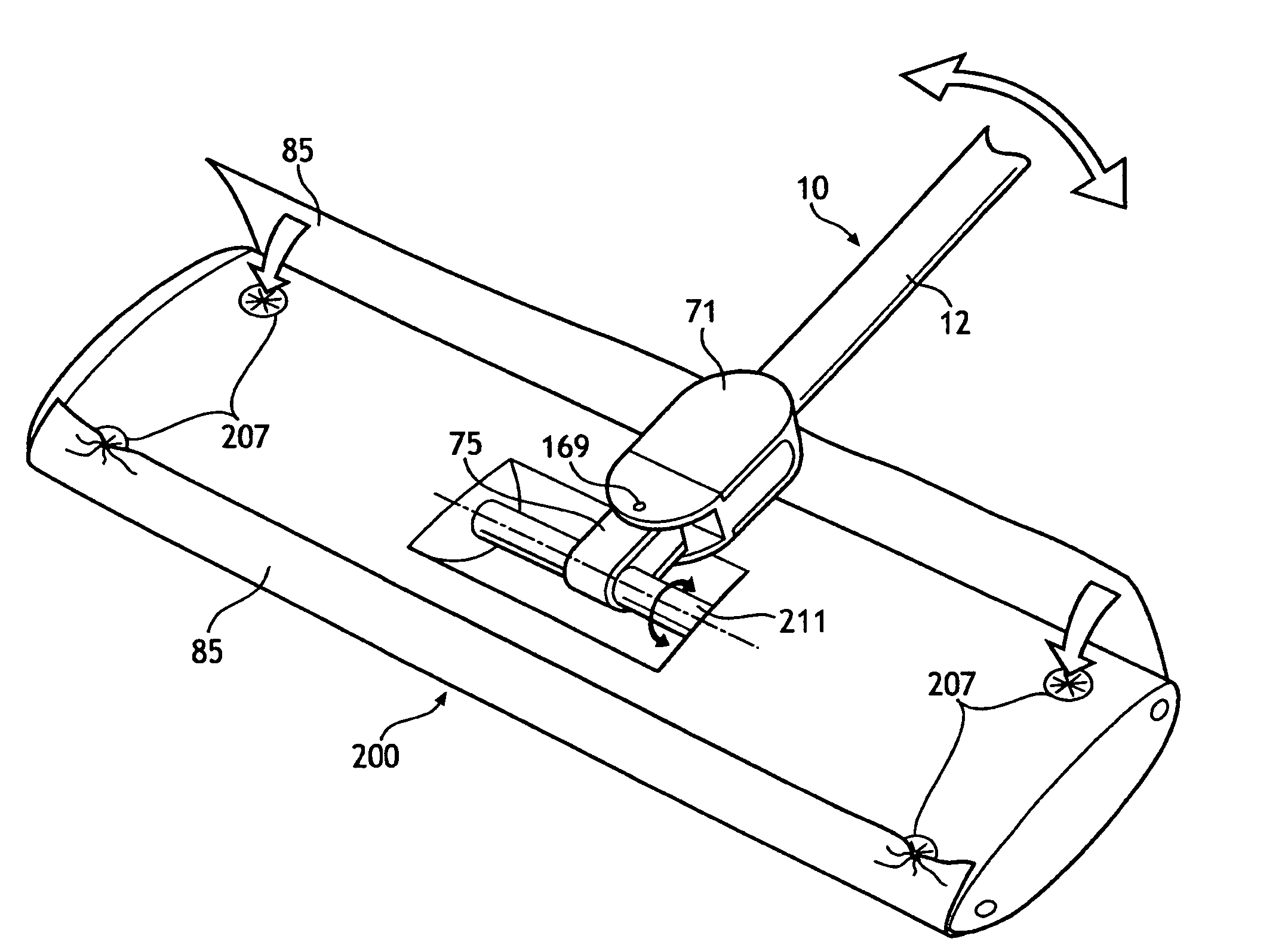
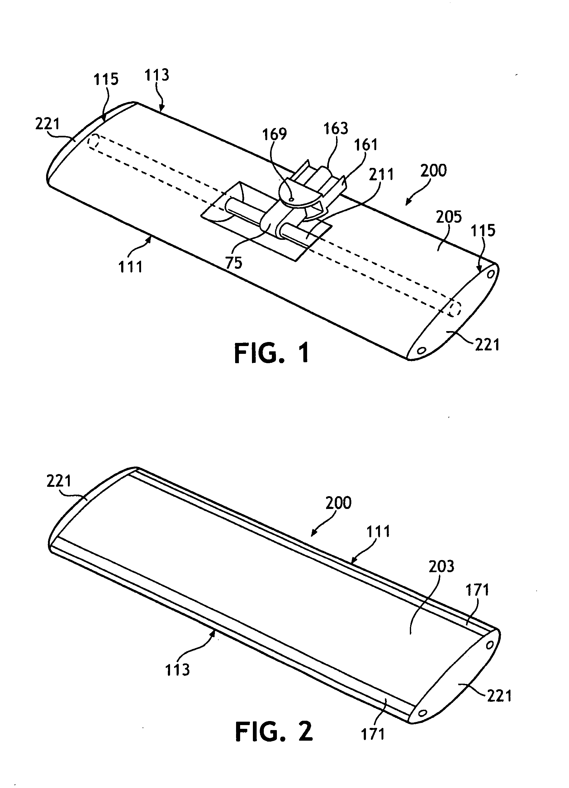
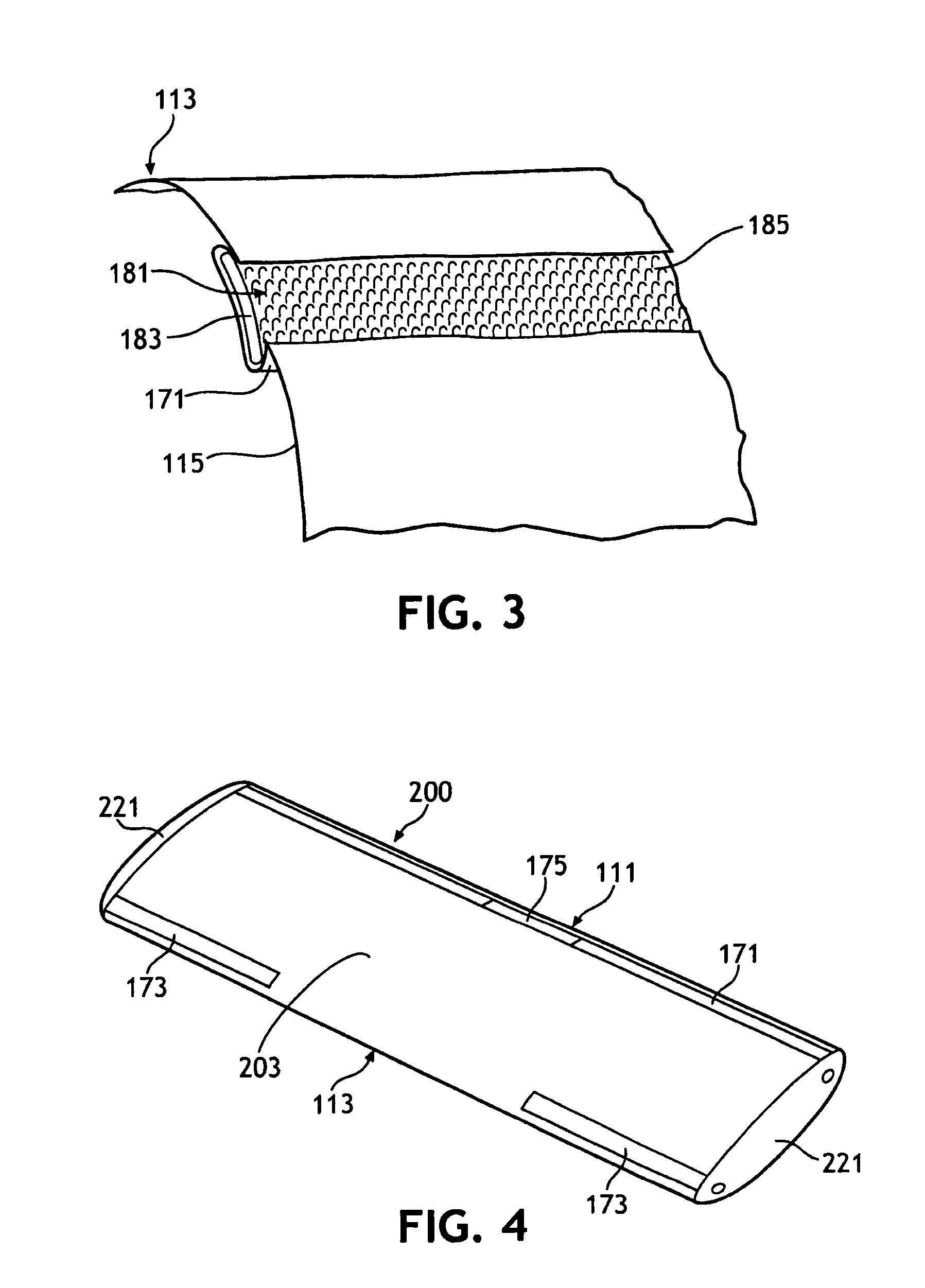
[0051]Referring to FIGS. 1-8C in general, the mop head 200 of the present invention includes a lower substrate support surface 203 to which a disposable cleansing substrate may be coupled during use of the mop head 200. One or more fastener channels 171 may be associated with the lower substrate support surface 203 and may be configured to contain one or more fastener strips 181. Such fastener strips 181 may be configured to couple the...


PUM

PropertyMeasurementUnit
Forceaaaaaaaaaa
Structureaaaaaaaaaa
Lengthaaaaaaaaaa

Abstract

A mop head assembly for use with a handle and a cleaning substrate is disclosed. The mop head assembly includes a lower substrate support surface, at least one fastener channel associated with the lower substrate support surface, and a fastener strip that can be inserted into the fastener channel. Such a fastener strip is configured to couple the lower substrate support surface to a cleaning substrate. The mop head assembly may include a cross-member configured such that forces applied from the handle through a central portion of mop head are distributed toward the end edges of the lower substrate support surface.

Description

BACKGROUND[0001]Various versions of floor mops are commonly available for the variety of cleaning needs in both commercial and domestic consumer environments. For example, cotton string floor dust mops are commonly seen cleaning the dust and debris from school and public building hallways. One problem with such cotton string dust mops is that the dirt and debris can build up in the cotton substrate. Such mop heads need to be regularly cleaned or replaced. Cleaning or replacing the substrate can be cumbersome and may result in significant added cost to the user.[0002]Smaller versions of such dust mops are readily available for consumer home use and utilize disposable cleaning substrates that are applied to the mop head. The disposable cleaning substrate is most commonly wrapped across the floor-contacting surface of such mop heads and both of the substrate's free ends are fastened to the upper surface of the mop head. Various methods have been used to fasten such substrates to these ...

Claims


Application Information

Patent Timeline
IPC IPC(8): A47L13/12A47L13/24
CPCA47L13/254A47L13/42A47L13/256
Inventor MORRIS, CAMERON RAYROSSIGNOL, STEPHANIE ANNNUKUTO, GEORGEGRIMARD, DENIS R.RIPPL, CARL G.LEE, MEEWHAWOON, PAULKROLL, RUSSELL J.LONDBORG, MARKHENSHAW, ROBERTREDDY, KIRAN K.MERRILL, THOMAS GLENNRUBIO-FLORES, JOSE RICARDO
Owner KIMBERLY-CLARK WORLDWIDE INC
Learn More