High-efficiency error detection and/or correction code

a correction code and error detection technology, applied in the field of high-efficiency error detection and/or correction codes, can solve the problems of inability unable to detect two errors, etc., to achieve the effect of easy decoding

Inactive Publication Date: 2005-11-01
STMICROELECTRONICS SRL
View PDF6 Cites 9 Cited by
  • Summary
  • Abstract
  • Description
  • Claims
  • Application Information

AI Technical Summary

Benefits of technology

[0019]The method implements an error detection and / or correction code that can be implemented in a simple way by an integrated circuit.
[0020]The method implements an error detection and / or correction code that enables easy decoding.

Problems solved by technology

and there is a single error in the received word, this means that the first detection bit C0 is erroneous.
A disadvantage of the Hamming code is that it cannot detect two errors.
Another disadvantage of the Hamming code is that the Hamming matrix is neither symmetrical nor regular.
Such jumps make difficult the forming of a circuit implementing the Hamming code as well as the syndrome decoding, that is, the determination of the erroneous bit.

Method used


Image

  • High-efficiency error detection and/or correction code
  • High-efficiency error detection and/or correction code
  • High-efficiency error detection and/or correction code

Examples


first embodiment

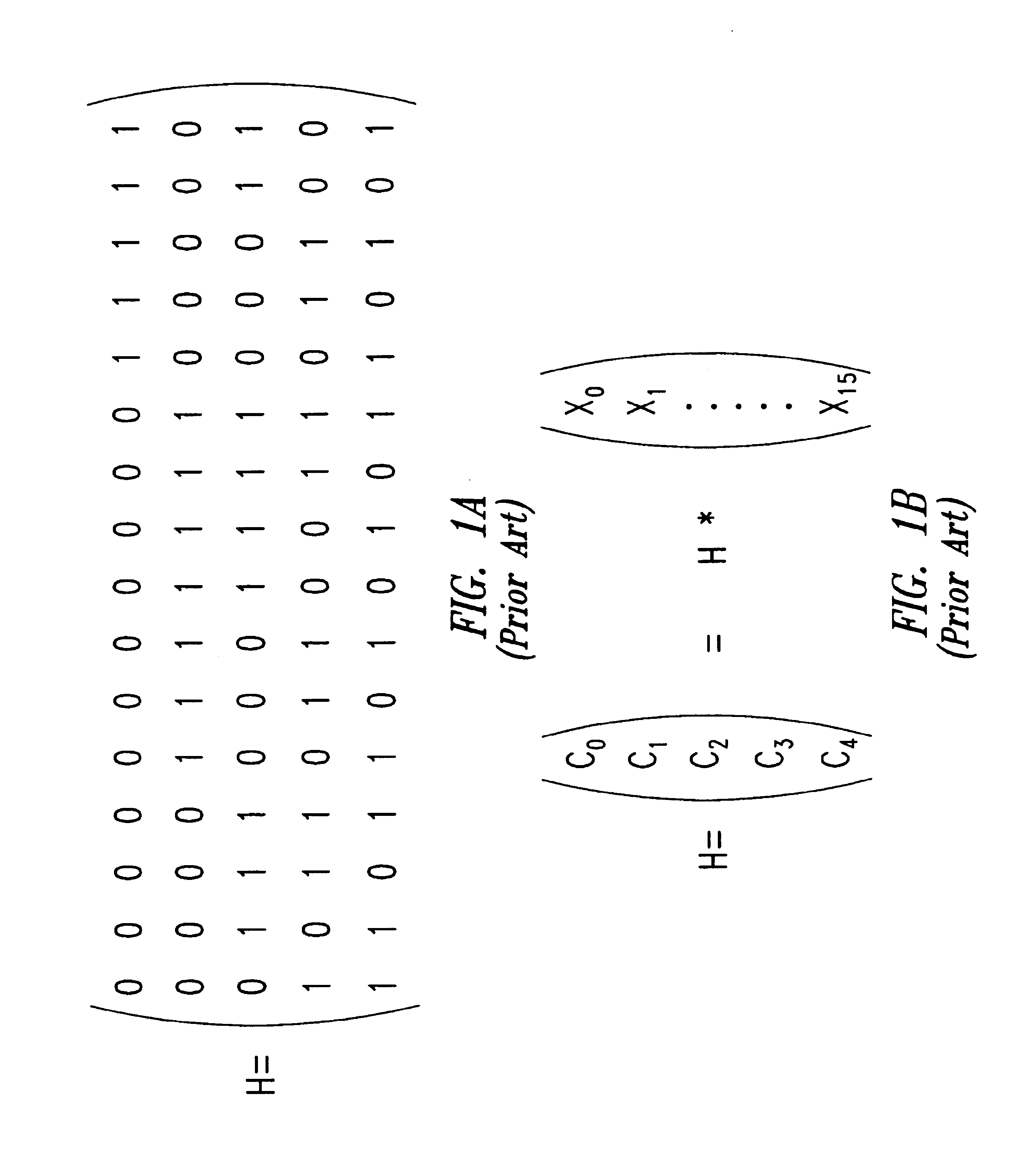
[0050]FIG. 3A illustrates a parity check matrix M1 used to calculate detection bits in the present invention.

[0051]Matrix M1 is a 5×16 matrix. It is intended for being multiplied by a vector representative of a 16-bit word to be coded to provide 5 error detection bits Ci. Matrix M1 is formed based on a repetitive pattern. The repetitive pattern is represented by a matrix G of dimensions 4×8 and is repeated twice. Matrix G is equal to: G=(11110000000011110011001101010101).

[0052]Matrix G is chosen so that each column of matrix G is different from another column of matrix G and, if any two columns of matrix G are added modulo 2, this provides no other column of matrix G. Thus, the logic addition of the second and third columns of matrix G provides (1001)⊕(1010)=(0011) [symbol ⊕ designates the XOR operation], which corresponds to no column of G. This is done to be able to detect two errors, as will be seen hereafter.

[0053]The two matrixes G, which form sub-matrixes of matrix M1, are pla...

second embodiment

[0093]FIGS. 5A, 5B, and 6 illustrate the present invention.

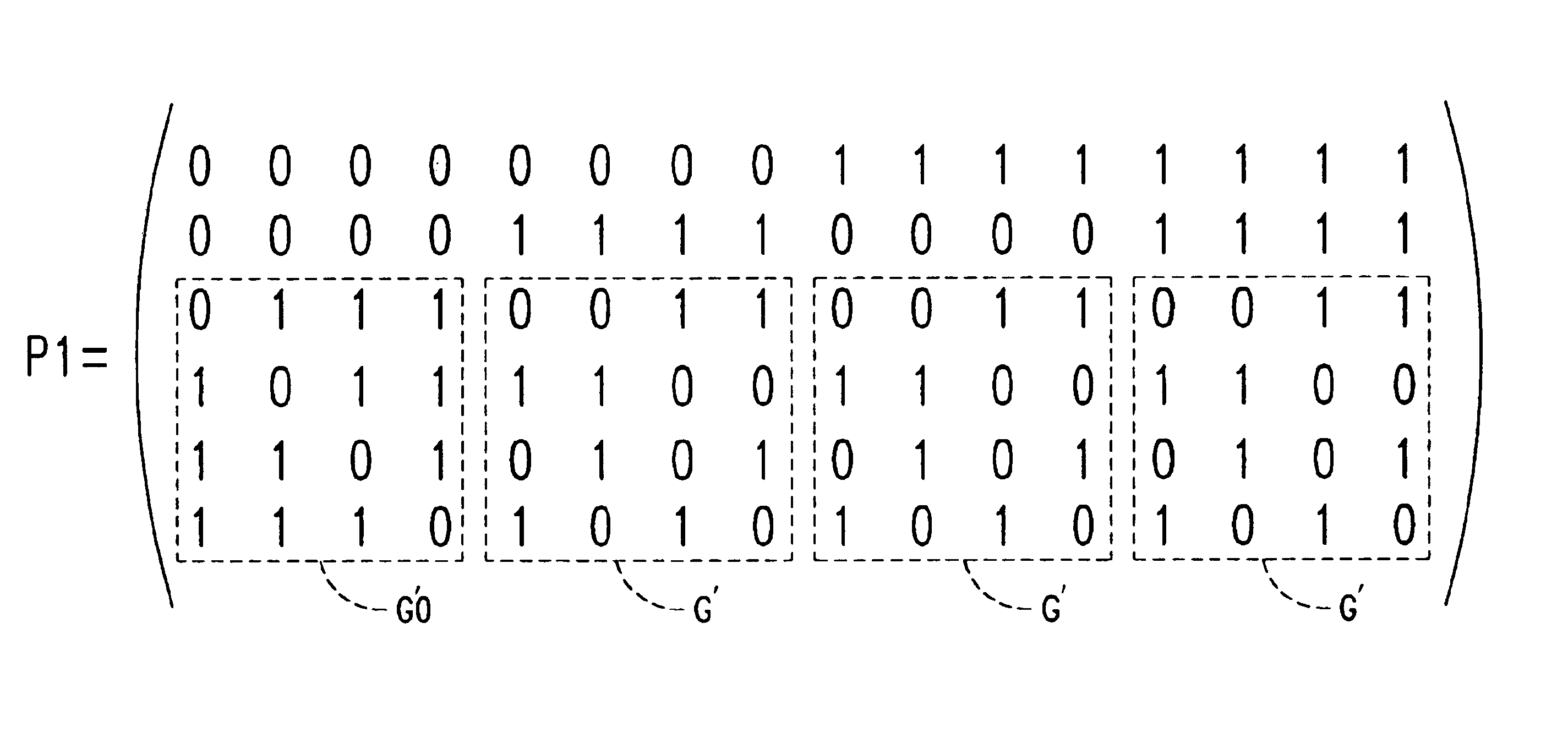
[0094]FIG. 5A illustrates a parity check matrix P1 for a 16-bit word to be coded. Matrix P1 is a matrix of dimensions 6×16.

[0095]The first 4×4 block located to the bottom left of matrix P1 is: G′⁢0=(0111101111011110).

[0096]Further, matrix P1 includes a repetitive pattern in the form: G′=(gg_⁢gggg⁢gg_g_⁢g⁢g_⁢gg⁢g_⁢g⁢g_),

with g=1, {overscore (g)} being the complement to 1 of g. G′ is a matrix chosen so that each column of matrix G′ is different from another column of matrix G′ and the sum modulo 2of two of the columns of matrixes G′ is never equal to one column of G′.

[0097]Matrixes G′ and G′0 are sub-matrixes of matrix P1, and they will be so designated when necessary hereafter.

[0098]In matrix P1, matrix G′ is present 3 times, one matrix G′ following another to occupy the rest of the last four lines of matrix P1. The line just above matrixes G′0 and G′ (second line of P1) is formed of a sequence of four “0s”, followed by four ...


PUM


Abstract

A method for determining r error detection bits of a word of m bits to be coded, including the step of calculating the product of a vector with m components representative of said word of m bits to be coded and of a parity check matrix. The parity check matrix includes a pattern matrix that may be repeated in said parity check matrix, and said pattern being chosen so that a sum modulo 2 of any two columns of said sub-matrix does not give as a result another column of said sub-matrix. Another method determines a syndrome using r error detection bits determined by the above method.

Description

BACKGROUND OF THE INVENTION[0001]1. Field of the Invention[0002]The present invention relates to error detection and / or correction codes, and in particular to linear codes of Hamming type.[0003]2. Description of the Related Art[0004]The Hamming code is an error detection and correction code used in many fields. Its use for transmission will be described, in the case where the data to be transmitted are in the form of 16-bit words.[0005]Let X be the word to be transmitted. X can be represented by a vector Xe, the 16 components X0, X1, . . . X15 of which correspond to the 16 bits of the word to be transmitted. Five error detection bits Ci (C0 . . . C4) are obtained by multiplying a parity check matrix H, called a Hamming matrix, of dimensions 5×16, by vector Xe in the form of a column vector.[0006]FIG. 1A illustrates Hamming matrix H for 16 bits and FIG. 1B illustrates how to obtain the detection bits. Calling hij the elements of matrix H, the error detection bits Ci are given by: Ci=...

Claims


Application Information

Patent Timeline
Patent Type & Authority Patents(United States)
IPC IPC(8): H03M13/13H03M13/00H03M13/15H03M13/29H03M13/19
CPCH03M13/19H03M13/6502
Inventor MURILLO, LAURENT
Owner STMICROELECTRONICS SRL
Why Eureka
Try Eureka