Fracture split method for connecting rod

a technology of fracture split and connecting rod, which is applied in the direction of connecting rod bearings, mechanical equipment, solid-state diffusion coating, etc., can solve the problems of reducing the degree of circularity of the surface forming the crankpin hole, deformation of the big end, and various problems

Active Publication Date: 2005-11-08
YAMAHA MOTOR CO LTD
View PDF9 Cites 23 Cited by
  • Summary
  • Abstract
  • Description
  • Claims
  • Application Information

AI Technical Summary

Problems solved by technology

Various problems can occur during the process of splitting the connecting rod into the rod and cap parts.
For instance, when the connecting rod is hardened for better performance, the high loading force necessary to break the big end into the rod and cap parts can deform the big end and decrease the degree of circularity of the surfaces forming the crankpin hole.
Also, if a high carbon material is used that is heat treated by quenching, the fracture split surfaces will be in the form of a grain boundary surface that is generally flat, making it difficult to obtain accurate alignment between the rod and cap parts.
However, this approach usually requires that the assist holes be accurate positioned, which increases production cost.
Another problem that can occur during the splitting process is the production of double fractures that result when fracture initiation occurs at more than one point along the break plane.
Such double fractures can cause tiny fractions of the fracture split surfaces to come off, mix into engine oil, and damage other components of the engine.
When this method is used, the jig generally has a complicated shape and requires a high degree of accuracy, which can again increase production costs.

Method used


Image

  • Fracture split method for connecting rod
  • Fracture split method for connecting rod
  • Fracture split method for connecting rod

Examples


Embodiment Construction

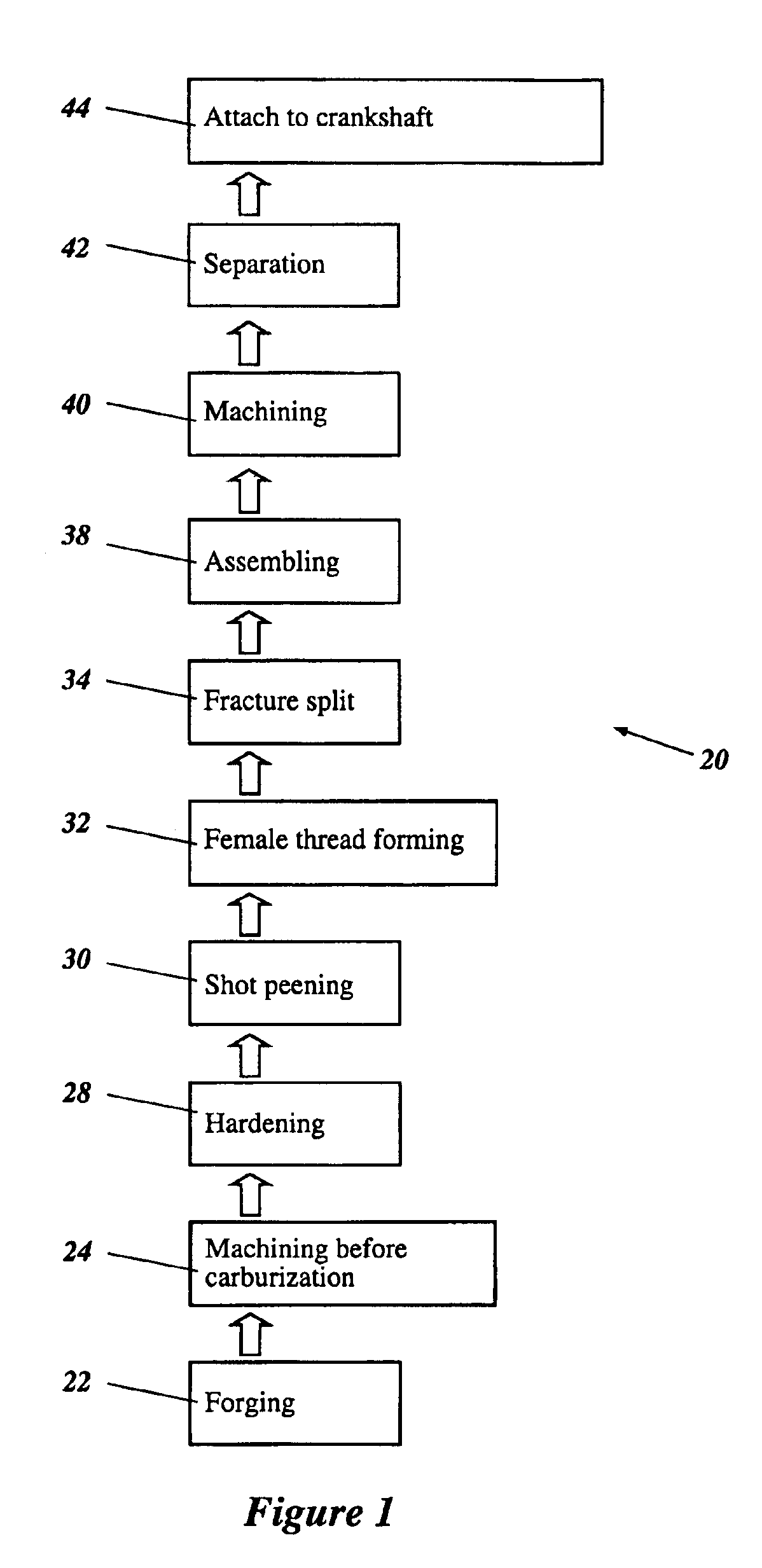
[0036]The manufacturing process can be used to produce a hardened component of an engine, such as, for example, a connecting rod. FIG. 1 illustrates the preferred manufacturing steps involved in producing a connecting rod in accordance with a preferred manufacturing method 20; however, various aspects and features of the invention can be readily adapted to produce various types of components for other products. Accordingly, the illustrated manufacturing method is not meant to limit the invention, but rather to disclose one embodiment that various aspects and features of the invention can take.

[0037]By way of an initial overview, the method 20 can start by providing a connecting rod blank. The connecting rod blank preferably is created by forging the connecting rod (Step 22) and then machining the connecting rod (Step 24). The method 20 also comprises one or more surface processing steps, such as, for example, surface hardening the connecting rod (Step 28) and shot peening the surfac...


PUM

PropertyMeasurementUnit
temperatureaaaaaaaaaa
thicknessaaaaaaaaaa
thicknessaaaaaaaaaa

Abstract

A connecting rod is formed using a method that includes providing a connecting rod blank. The connecting rod blank has a rod section disposed between a big end and a small end. The big end has a first hole generally sized to receive a crankpin of a crankshaft and at least one second hole generally sized to receive a bolt, wherein the axes of the first and second holes are generally normal to each other. The big end of the connecting rod has a dividing plane that extends through both the first and second holes. The connecting rod blank is processed by hardening at least the big end to a sufficient depth such that a first region of the big end lying between the first and second holes at the dividing plane is hardened, while leaving a substantial second region of the big end at the dividing plane generally unhardened. The connecting rod blank is further processed by splitting the big end along the dividing plane to produce a rod part fracture surface and a cap part fracture surface.

Description

PRIORITY INFORMATION[0001]This application is based on and claims priority under 35 U.S.C. § 119 to Japanese Patent Application No. 2002-206522 filed on Jul. 16, 2002, the entire contents of which is hereby expressly incorporated by reference herein.BACKGROUND OF THE INVENTION[0002]1. Field of the Invention[0003]The present invention is directed to a method of forming a fracture split in a part, and more specifically, to a method of forming a fracture split in the big end of a connecting rod. The present invention is also directed to a connecting rod having a fracture surface at the big end having both hardened and unhardened portions.[0004]2. Description of the Related Art[0005]Connecting rods are typically attached to the crankshaft of an engine by fabricating the big end of the connecting rod can be separated with a cap part that is separable from the rod part. Typically, the finished cap part and rod part were fabricated separately and then bolted together around a crankshaft pi...

Claims


Application Information

Patent Timeline
Patent Type & Authority Patents(United States)
IPC IPC(8): F16C9/00F16C9/04F16C7/02C23C8/20
CPCF16C9/045Y10T29/49286Y10T29/49288Y10T29/4979
Inventor KUBOTA, TSUYOSHIIWASAKI, SHINYAISOBE, TSUNEO
Owner YAMAHA MOTOR CO LTD
Why Eureka
Try Eureka