Method and apparatus for interconnected, rolling rig and oilfield building(s)

Inactive Publication Date: 2005-11-08
WEATHERFORD CANADA
View PDF17 Cites 60 Cited by
  • Summary
  • Abstract
  • Description
  • Claims
  • Application Information

AI Technical Summary

Benefits of technology

[0008]A conventional land drilling rig is slightly modified to adapt for efficient pad drilling. The conventional land drilling rig is interconnected to form a somewhat rigid convoy. The interconnected drilling rig is placed on top of matting. The matting has rollers to facilitate movement of

Problems solved by technology

Large lease locations, difficulties in transferring gasified mud, the need to constru

Method used


Image

  • Method and apparatus for interconnected, rolling rig and oilfield building(s)
  • Method and apparatus for interconnected, rolling rig and oilfield building(s)
  • Method and apparatus for interconnected, rolling rig and oilfield building(s)

Examples


Embodiment Construction

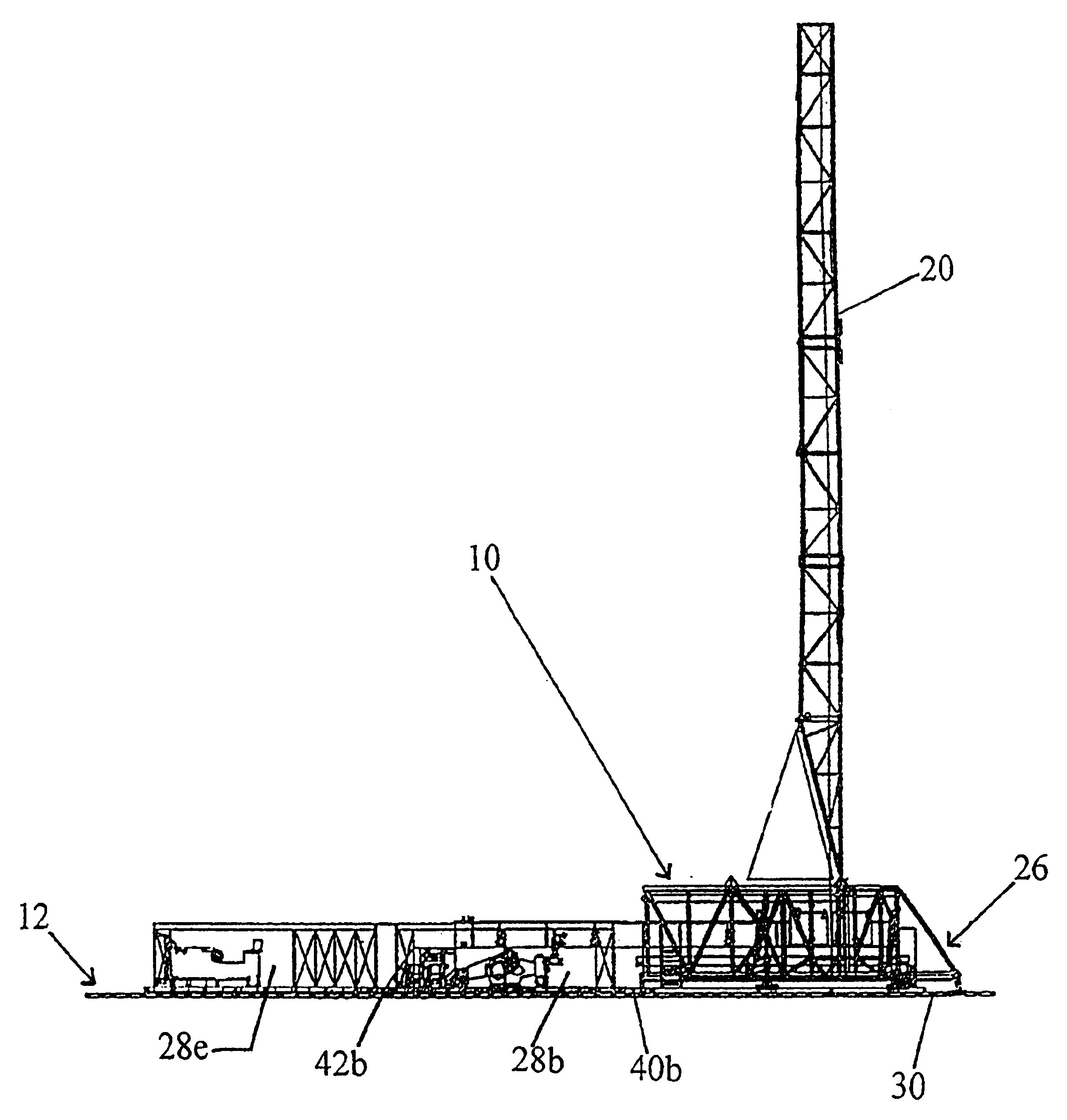
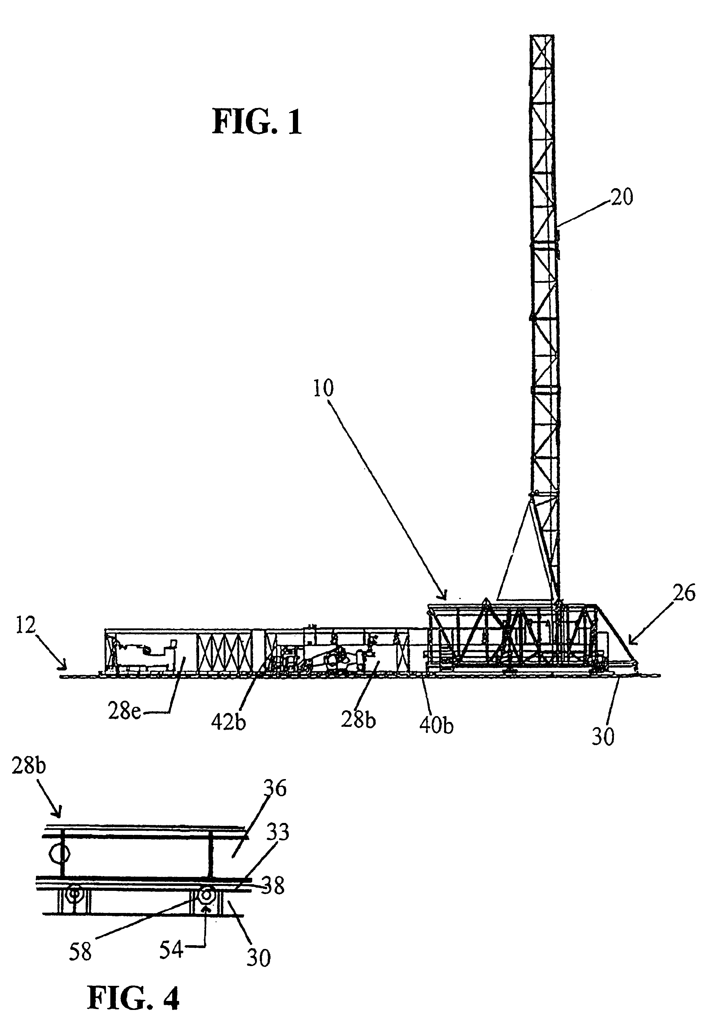
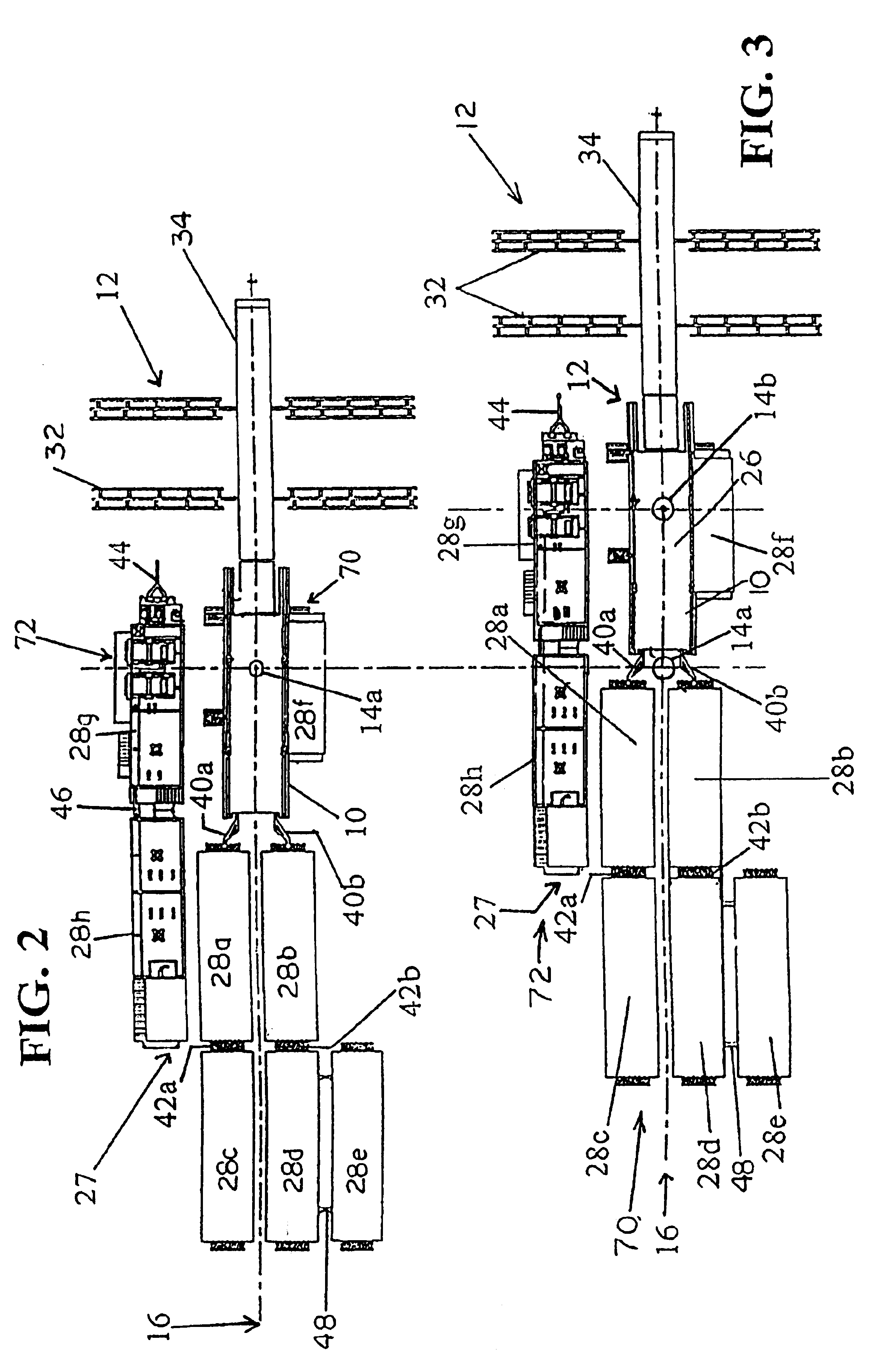
[0017]Referring to FIGS. 1-3 a drilling rig 10 is shown for a cluster of wells with wellheads 14a and 14b (there may be several more wells located along the well line 16 of the wells). The drilling rig 10 and oilfield buildings 28a-f are converted into an integral system or convoy 70.

[0018]For comparison, a prior art land drilling rig 10 for pad work is shown in FIG. 3A. The prior art drilling rig 10 with wellheads 14a, 14b, etc. has a mobile complex 80 which is separate from a stationary complex 82. The mobile complex moves along the well line 16. The stationary complex 82 is set to the side of the drilling location and includes several oilfield buildings. Suitcases 84a, 84b (typically, more than two are utilized) carry electrical cables and mud hoses (both not shown) from the stationary complex 82 to the varying location of the mobile complex 80.

[0019]Referring back to FIGS. 1-3, the land drilling rig 10 of the present invention, in one embodiment, generally includes a mast / crown ...


PUM


Abstract

A conventional land drilling rig is interconnected to the substructure for an oilfield pad location. The interconnected drilling rig is placed on top of matting. The matting has embedded rollers to facilitate movement of the drilling rig as a “convoy” across the mat from one wellhead to another wellhead. The buildings in the mud tank system may also be interconnected and move in a separate convoy but in tandem with the first convoy.

Description

CROSS-REFERENCE TO RELATED APPLICATIONS[0001]This application claims the benefit of U.S. provisional application No. 60 / 327,077 filed Oct. 4, 2001.STATEMENTS REGARDING FEDERALLY SPONSOR RESEARCH OR DEVELOPMENT[0002]Not applicable.REFERENCE TO A MICROFICHE APPENDIX[0003]Not applicable.BACKGROUND OF THE INVENTION[0004]Description of the Related Art[0005]In certain land drilling locations a number of wells are drilled from the same surface location, referred to as a “pad.” The wells are drilled directionally to access oil reservoirs that extend horizontally from the pad. In order to optimize the time used to move the rig to the next well on a pad, it is necessary to skid the drilling rig from one well on the pad to another well location on the same pad. The distance between the wells on the same pad varies but can, for example, be in the order of about ten meters.[0006]The land drilling rig used for drilling wells on the pad is comprised of a number of support modules containing such e...

Claims


Application Information

Patent Timeline
IPC IPC(8): E21B7/02E02B17/00E04H5/02E04H12/18E21B15/00
CPCE21B15/00E21B15/003
Inventor CONN, ORLIE
Owner WEATHERFORD CANADA
Why Eureka
Try Eureka