Method of determining characteristics of a tire from stresses
a technology of stress and tire, applied in the field of vehicles, can solve the problems of modification of tire deformation and distribution of stress in the bead
- Summary
- Abstract
- Description
- Claims
- Application Information
AI Technical Summary
Benefits of technology
Problems solved by technology
Method used
Image
Examples
example 1
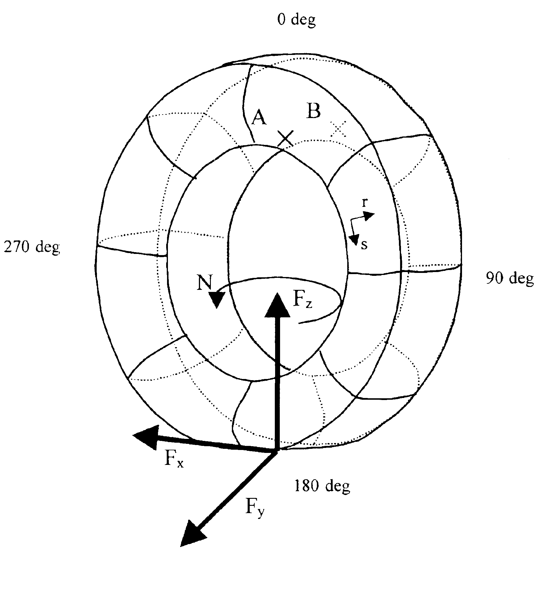
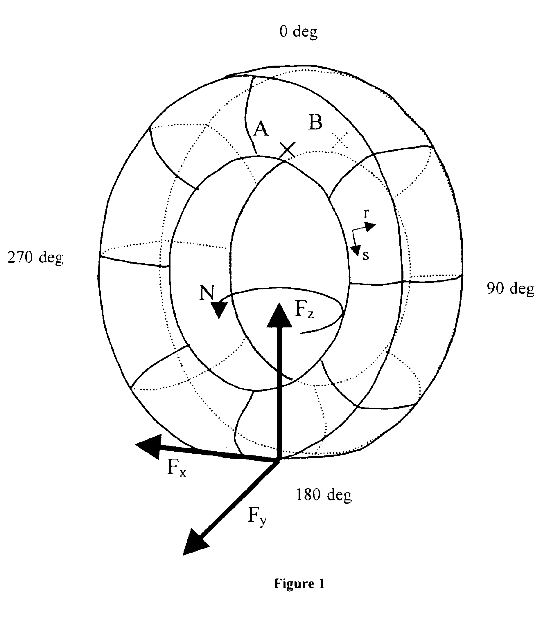
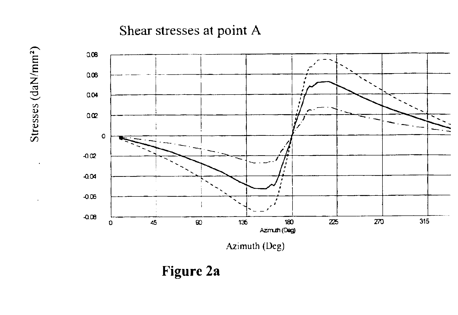
[0080]The intention is to estimate the components of the forces which are applied in the contact area, and the self-alignment torque, on the basis of measurements of the circumferential shear stress measured in one bead of the tire, at three azimuths. The measurement azimuths are selected in the following way:
[0081]One of the azimuths corresponds to the middle of the contact area or the azimuth of the point opposite to the contact area (azimuth 180°). Let Vc be the value measured at this point.
[0082]The other two azimuths are symmetrical with respect to the azimuth of the center of the contact area. (180°+α° and 180°−α°). Let V1 and V2 be the values measured at these points.
[0083]According to the observations above:
[0084]V2−V1 makes it possible to estimate the imbalance between the entry of the contact area and the exit. This value will be principally linked with the component Fz. An estimate of Fz is given by fz(r2V2−r1V1), where r1 and r2 are positive real coefficients and fz is a...
example 2
[0088]The intention is to estimate the components of the forces which are applied in the contact area, and the self-alignment torque, on the basis of measurements of the circumferential shear stress in the bead on one side of the tire, measured at five azimuths. The measurement azimuths are selected in the following way:[0089]One of the azimuths corresponds to the middle of the contact area (azimuth 180°) or to the opposite side from the contact area (azimuth 0°). Let Vc be the value measured at this point.
[0090]Two other azimuths are symmetrical with respect to the azimuth of the center of the contact area. (180°+α° and 180°−α°). Let V1 and V2 be the values measured at these points.
[0091]The final two azimuths are symmetrical with respect to the azimuth of the center contact area. (180°+β° and 180°−β°). Let V3 and V4 be the values measured at these points.
[0092]Combinations which are of the same nature as, but a little more complex than, those explained in Example 1 make it possibl...
example 3
[0094]The intention is to estimate the components of the forces which are applied in the contact area, and the self-alignment torque, on the basis of measurements of the circumferential shear stress of both beads of the tire, measured at two azimuths on each bead. The measurement azimuths are selected symmetrically with respect to the azimuth of the center of the contact area (180°+α° and 180°−α°). So that Fx can be estimated, α must not be equal to 0° or 180°. Let V11 and V21 be the values measured at these azimuths on the first bead, and V12 and V22 the values measured at these azimuths on the second bead.
[0095]Thanks to these four values, it is possible to determine the components by using decomposition according to the azimuth-related and bead-related parities:
[0096]V11+V12+V21+V22 gives the azimuth-related and bead-related even component. This combination is therefore directly linked with Fx. An estimate of Fx is given by fx(a1V11+a2V21+b1V12+b2V22), where a1, a2, b1 and b2 are...
PUM
 Abstract
Description
Claims
Application Information
 - R&D
- Intellectual Property
- Life Sciences
- Materials
- Tech Scout
- Unparalleled Data Quality
- Higher Quality Content
- 60% Fewer Hallucinations
Browse by: Latest US Patents, China's latest patents, Technical Efficacy Thesaurus, Application Domain, Technology Topic, Popular Technical Reports.
© 2025 PatSnap. All rights reserved.Legal|Privacy policy|Modern Slavery Act Transparency Statement|Sitemap|About US| Contact US: help@patsnap.com


