Subsea wellhead landing clamp and slip bowl assembly

a technology for landing clamps and wellheads, which is applied in the direction of sealing/packing, drilling pipes, and wellbore/well accessories, etc. it can solve the problems of high cost of repairs, and inability to prevent the plate from moving side to side on the clamp. , to achieve the effect of convenient opening and disengagement, easy to open

Inactive Publication Date: 2005-11-08
LAY JR MILFORD
View PDF9 Cites 19 Cited by
  • Summary
  • Abstract
  • Description
  • Claims
  • Application Information

AI Technical Summary

Problems solved by technology

If damaged, repairs can be very expensive, in addition to the rig downtime which must be incurred for the repair.
However, the usual operations associated with running the subsea wellhead and surface casing string, and cementing the surface casing string, create numerous opportunities for damage to the subsea wellhead seal area.
This plate had a U-shaped cutout from its center to an edge, to permit it to be removed from around the drill pipe; however, no provision was made to prevent the plate from moving side to side on the clamp.
This prior art apparatus presented several problems and drawbacks.
First, bolting and unbolting the two halves of the clamp was time consuming and posed an increased risk of injury to rig workers.
Second, the drill pipe slip bowl was not secured to prevent side-to-side movement within the subsea wellhead, since it was simply resting atop the base plate; therefore, particularly with the rocking movement often present on a floating drilling rig, the drill pipe cementing string was subject to striking the inner wall of the subsea wellhead bore, and more importantly to striking and damaging the bevel seal area of the subsea wellhead.

Method used


Image

  • Subsea wellhead landing clamp and slip bowl assembly
  • Subsea wellhead landing clamp and slip bowl assembly
  • Subsea wellhead landing clamp and slip bowl assembly

Examples


Embodiment Construction

[0020]While those skilled in the art will recognize different embodiments as being possible while not exceeding the scope of the present invention, the following description will illustrate some of the presently preferred embodiments of the invention.

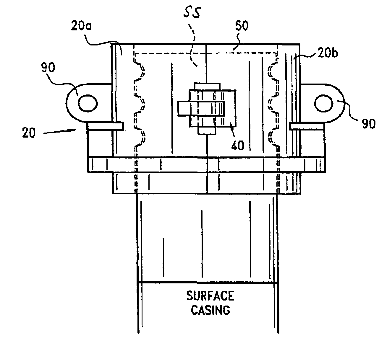
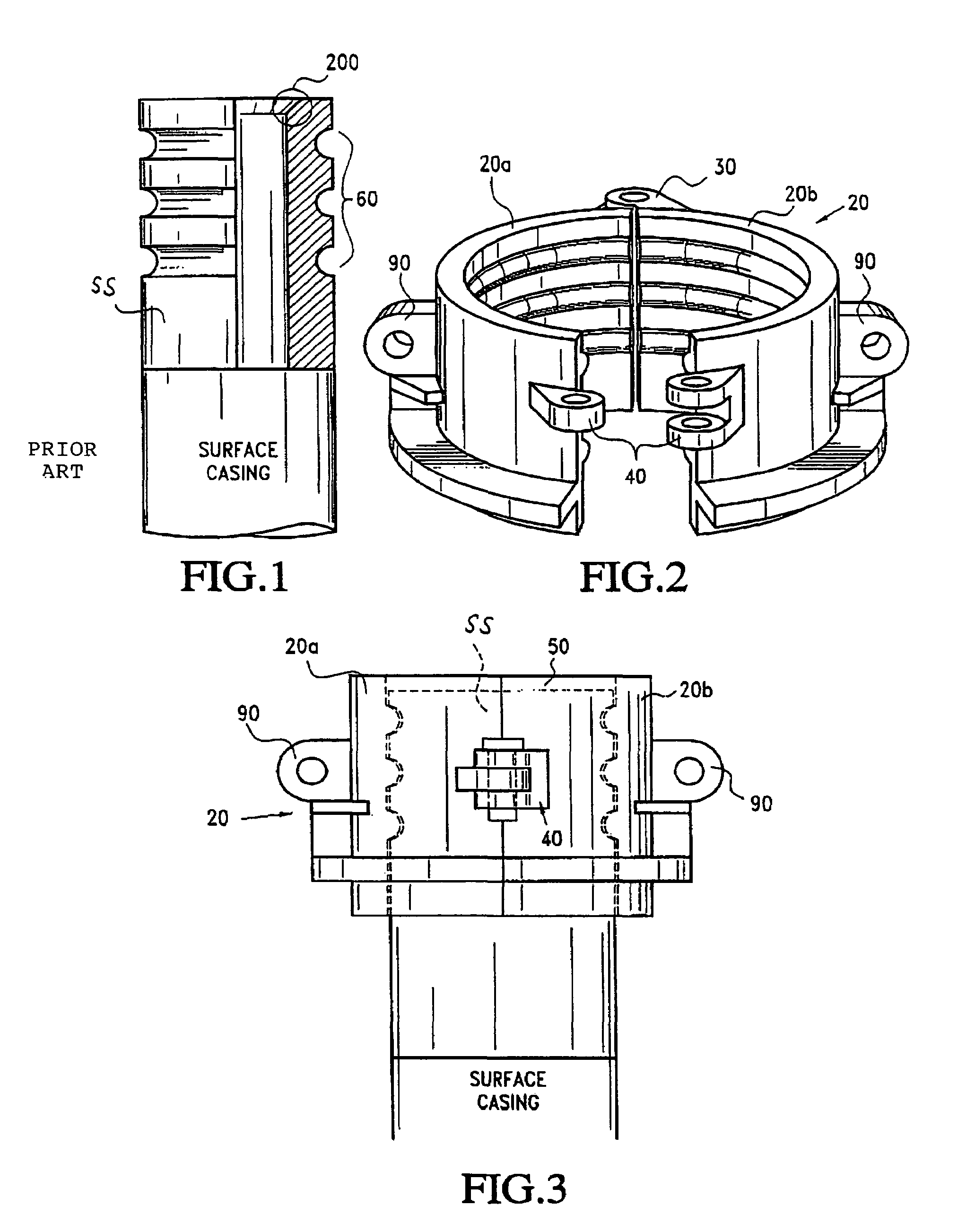
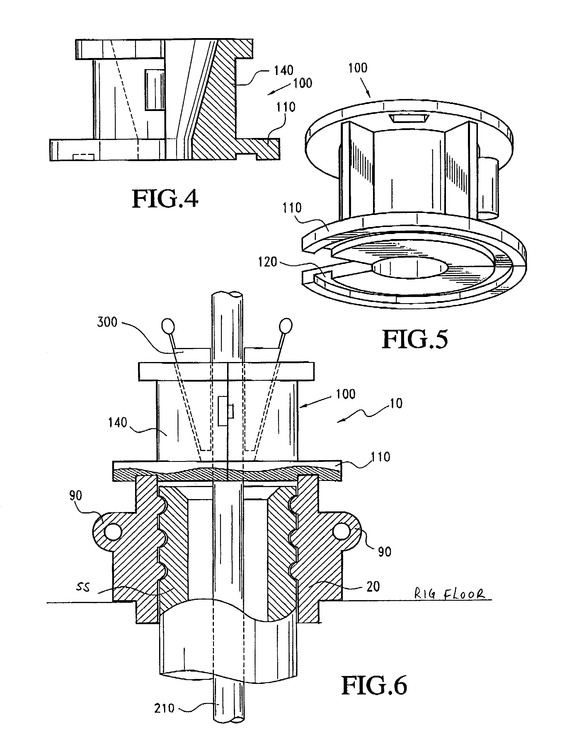
[0021]Referring to FIGS. 1–6: FIG. 1 shows a typical subsea wellhead SS attached to a section of surface casing. The apparatus 10 of the present invention comprises a hinged clamp 20 comprising two clamp halves 20a and 20b, each having a substantially half-circle cutout therein. Clamp 20 has a hinge 30 about which clamp halves 20a and 20b may rotate, between open and closed positions. FIG. 2 is a perspective view of clamp 20 in an open position. A fastener 40 joins clamp halves 20a and 20b together in the closed position. In the closed position, the half circle cutouts form a circular bore 50. In a presently preferred embodiment, fastener 40 comprises two pairs of aligned ears having holes therethrough, through which a pin can be placed...


PUM


Abstract

A clamp for supporting a subsea wellhead and attached casing string preparatory to installing same in a well, and slip bowl assembly for running a drill pipe cementing string inside the casing string. The clamp comprises two hinged together clamp halves with a connector to permit the clamp to be locked about a subsea wellhead. Half-circle cutouts in each clamp half form a clamp bore when the clamp is closed. The clamp bore has a grooved profile to mate with a grooved profile on the exterior of the subsea wellhead. When the subsea wellhead is clamped in place, with the clamp resting on the rig floor, a slip bowl assembly having a grooved base plate is placed atop the clamp.

Description

BACKGROUND[0001]1. Field of Art[0002]This invention relates to apparatus used in the drilling of earthen boreholes, commonly called “wells,” from floating drilling vessels. With further specificity, this invention relates to apparatus used in connection with the deployment of subsea wellheads, the protection of critical sealing areas thereon, and the placement and cementing of the associated casing string.[0003]2. Related Art[0004]Onshore or in shallow offshore waters, wellhead equipment is situated so as to be fairly close to (although nearly always somewhat below) the level of the rig floor. In particular, on offshore wells in water shallow enough that a bottom-supported, jackup type drilling rig can be used, a length of conductor casing extends upwardly from the sea floor, and helps support the wellhead which is generally mounted on the surface casing string, above the surface of the water a desired distance. The production “tree” (a multiple valve assembly) is therefore situated...

Claims


Application Information

Patent Timeline
Patent Type & Authority Patents(United States)
IPC IPC(8): E21B19/00E21B33/03E21B17/02E21B33/038
CPCE21B33/038
Inventor LAY, JR., MILFORD
Owner LAY JR MILFORD
Why Eureka
Try Eureka