Descent controller with safety brake

a technology of safety brake and descent controller, which is applied in the field of safety devices, can solve the problems of not having safety provisions to automatically control the descent or prevent the freefall of the user, and the operation of improved patented devices can be difficult, so as to prevent accidental freefall

Inactive Publication Date: 2005-11-08
OSTROBROD MEYER
View PDF17 Cites 32 Cited by
  • Summary
  • Abstract
  • Description
  • Claims
  • Application Information

AI Technical Summary

Benefits of technology

[0014]In accordance with the illustrative embodiments demonstrating features and advantages of the present invention, there is provided a descent controller for lowering a workman or other person along a vertically extending rope from an elevated position to a relatively lower position includes a friction device that may be in the form of a cylinder having a plurality of turns of rope wrapped therearound or a plurality of spaced apart horizontal bars with the rope woven between the bars. The friction device interacts with said rope to retard the movement of the controller along the rope. A lever operated pawl is mounted beneath the friction device and is used by the workman to applying an adjustable force on said rope in order to control his descent down the rope. A centrifugal brake is mounted below the lever centrifugal brake. The centrifugal brake includes a wheel mounted for rotation and has the rope passing around at least a portion of said wheel. Included within the brake is a pawl brake mounted for rotation with the wheel and a fixed stop member. Upon sensing rapid rotation of the wheel, the pawl brake moves outwardly by centrifugal force to engage the fixed stop member and applies a positive stopping force on the wheel to prevent movement of the descent controller relative to said rope thereby preventing accidental freefall.

Problems solved by technology

While devices such as shown in the Forest patent have provided some benefit, they take some skill and experience to operate properly.
Furthermore, should the workman make a mistake or be injured, there are no safety provisions for automatically controlling his descent or for preventing freefall.
These improved patented devices can still be difficult to operate because of the manner in which they must be manipulated to control ones descent.
In addition, and perhaps more importantly, none of the Forrest or Varner et al. devices includes a mechanism such as an additional safety brake or the like.
While positive safety brakes are known, none has ever been combined with a descent controller.

Method used


Image

  • Descent controller with safety brake
  • Descent controller with safety brake
  • Descent controller with safety brake

Examples


Embodiment Construction

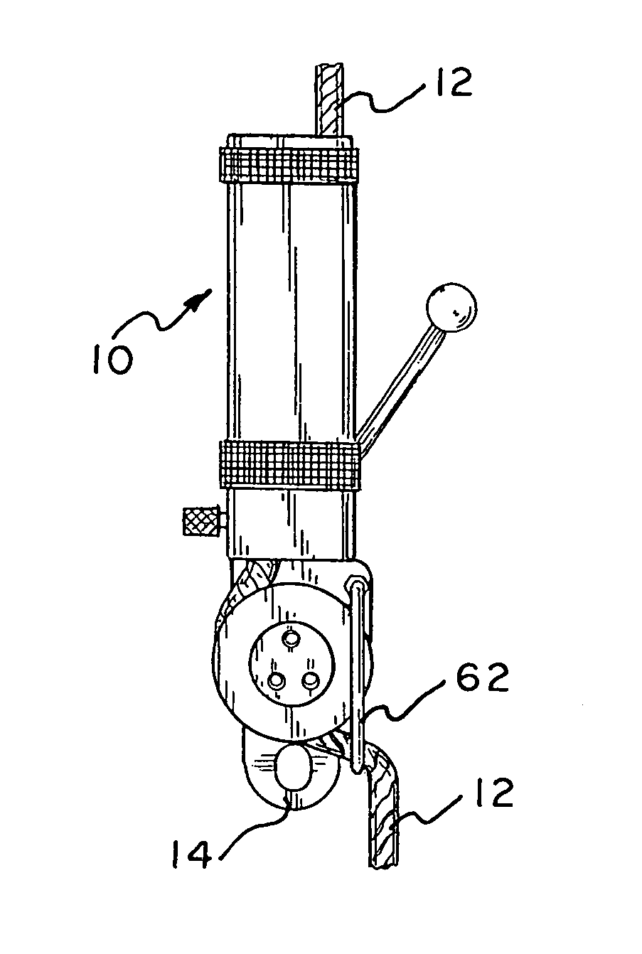
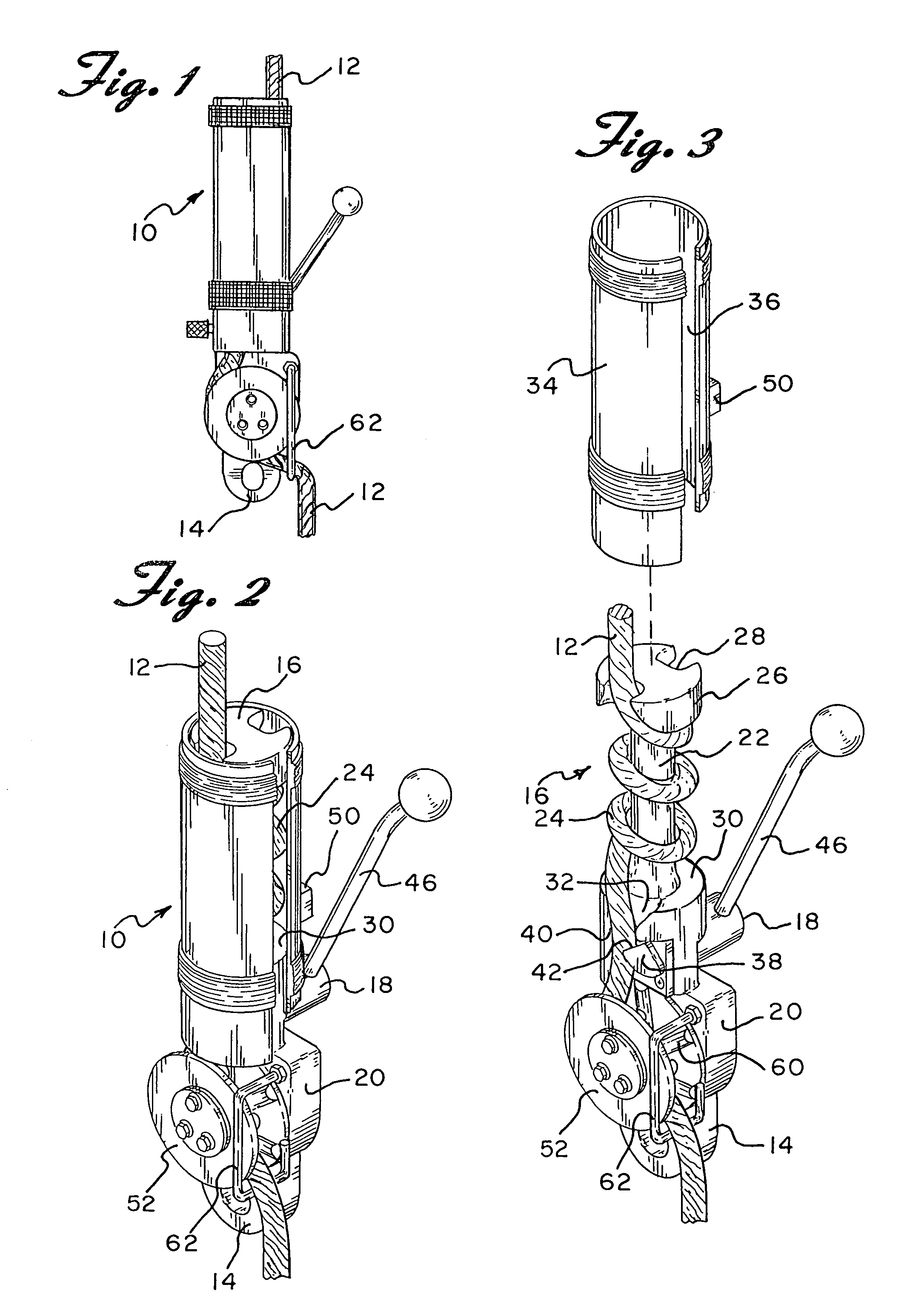
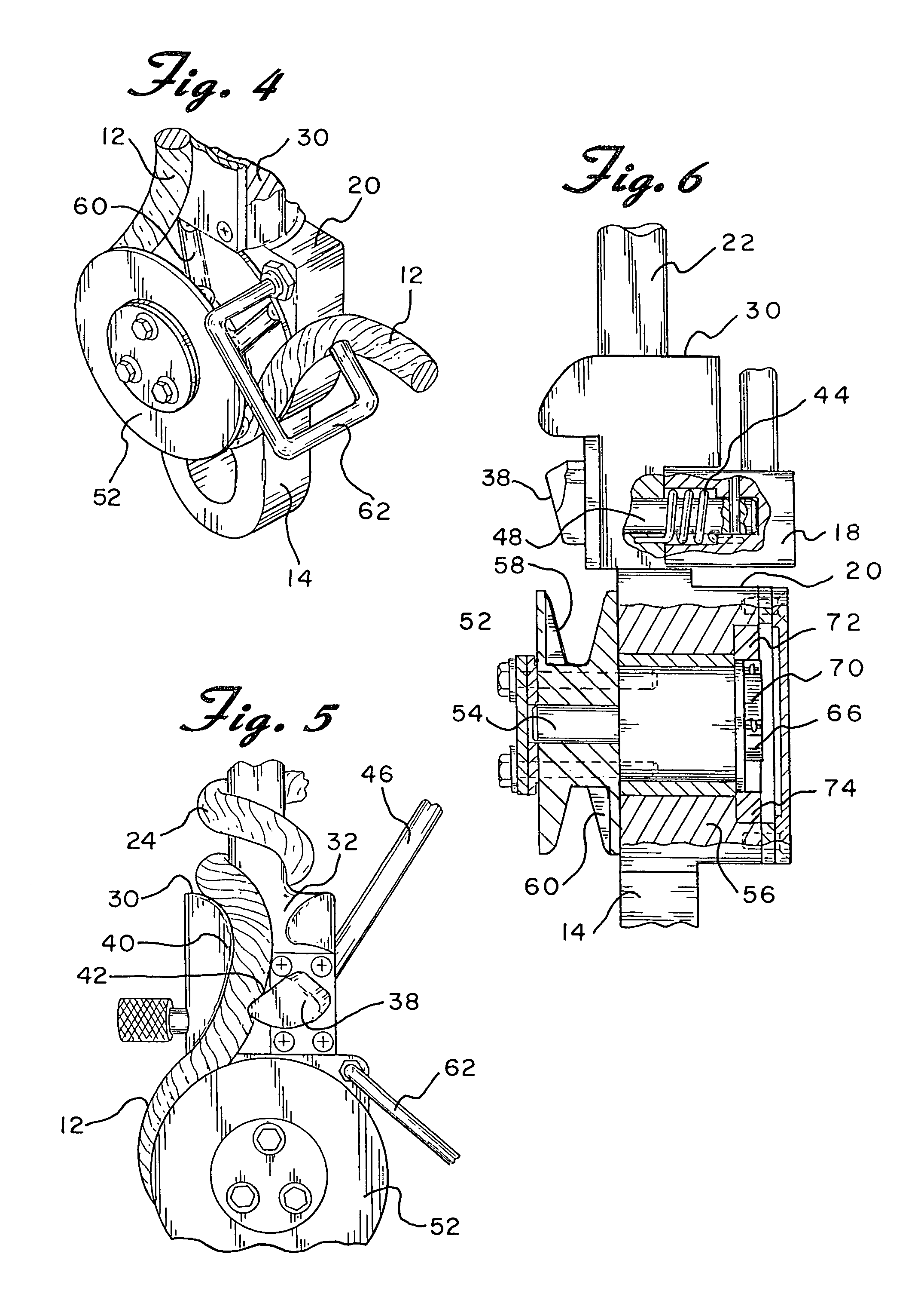
[0027]Referring now to the drawings in detail wherein like reference numerals have been used throughout the various figures to designate like elements, there is shown in FIGS. 1 and 2 a descent controller with a safety brake designated generally as 10. The descent controller 10 is shown attached to a rope 12 that has its upper end connected to the top of a building or other elevated structure and which hangs straight downwardly. As is conventional in the art, a workman wearing a harness will connect himself through the use of a carabiner or the like to the eyebolt 14 located at the bottom of the descent controller 10.

[0028]All of the foregoing general description of the descent controller 10 and the manner in which it is used are well known in the art. While the present invention is an improvement on prior devices of the same class, the general use and purpose of the invention is well known. It is generally used by a workman or other person to lower himself from an elevated position...


PUM


Abstract

A descent controller for lowering a workman or other person along a vertically extending rope from an elevated position to a relatively lower position includes a friction device that may be in the form of a cylinder having a plurality of turns of rope wrapped therearound or a plurality of spaced apart horizontal bars with the rope woven between the bars. The friction device interacts with said rope to retard the movement of the controller along the rope. A lever operated pawl is mounted beneath the friction device and is used by the workman to applying an adjustable force on said rope in order to control his descent down the rope. A centrifugal brake is mounted below the lever centrifugal brake. The centrifugal brake includes a wheel mounted for rotation and has the rope passing around at least a portion of said wheel. Included within the brake is a pawl brake mounted for rotation with the wheel and a fixed stop member. Upon sensing rapid rotation of the wheel, the pawl brake moves outwardly by centrifugal force to engage the fixed stop member and applies a positive stopping force on the wheel to prevent movement of the descent controller relative to said rope thereby preventing accidental freefall.

Description

CROSS-REFERENCE TO RELATED APPLICATIONS[0001]This application is a continuation of U.S. patent application Ser. No. 10 / 439,212, filed May 15, 2003, now U.S. Pat. No. 6,814,185.BACKGROUND OF THE INVENTION[0002]The present invention is directed toward a safety apparatus and more particularly toward a safety apparatus in the form of a descent controller used by a workman or other person to control his descent down a rope. The descent controller of the present invention also includes a centrifugal brake that prevents the rapid descent of the workman.[0003]Descent control devices have been developed, all with the objective of lowering a person or load from a higher to a lower elevation. These devices have taken many forms and have utilized a variety of elements capable of providing a mechanical advantage together with a braking mechanism. Safety features, such as deadman and panic control features, are equally important, particularly when the device is used for descent, escape, or rescue...

Claims


Application Information

Patent Timeline
Patent Type & Authority Patents(United States)
IPC IPC(8): A62B1/14A62B1/00
CPCA62B1/14
Inventor OSTROBROD, MEYER
Owner OSTROBROD MEYER
Why Eureka
Try Eureka