Method and apparatus for synchronized slotted optical burst switching

Inactive Publication Date: 2005-11-08
RPX CORP
View PDF8 Cites 41 Cited by
  • Summary
  • Abstract
  • Description
  • Claims
  • Application Information

AI Technical Summary

Benefits of technology

[0146]One advantage of using in-band transmission of control and data is that the architecture is closer t

Problems solved by technology

However, the increased capacity creates a serious mismatch with current electronic switching technologies that are capable of switching data rates up to a few gigabits per second, as opposed to the multiple terabit per second capability of DWDM.
This could lead to a significant loss of statistical multiplexing efficiency when the parallel channels are used simply as a collection of independent links, rather than as a shared resource.
Differe

Method used


Image

  • Method and apparatus for synchronized slotted optical burst switching
  • Method and apparatus for synchronized slotted optical burst switching
  • Method and apparatus for synchronized slotted optical burst switching

Examples


Embodiment Construction

[0049]The present invention is best understood in relation to FIGS. 1–33 of the drawings, like numerals being used for like elements of the various drawings.

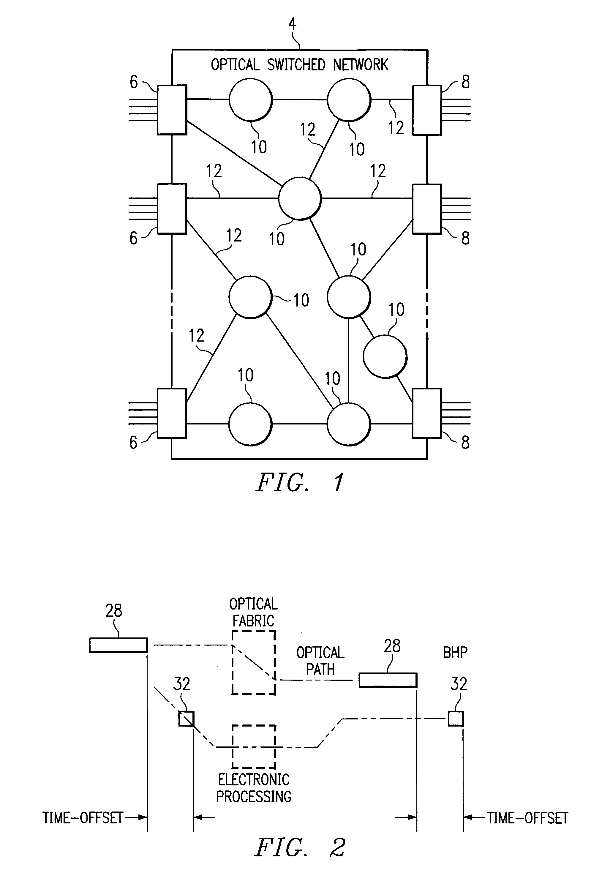
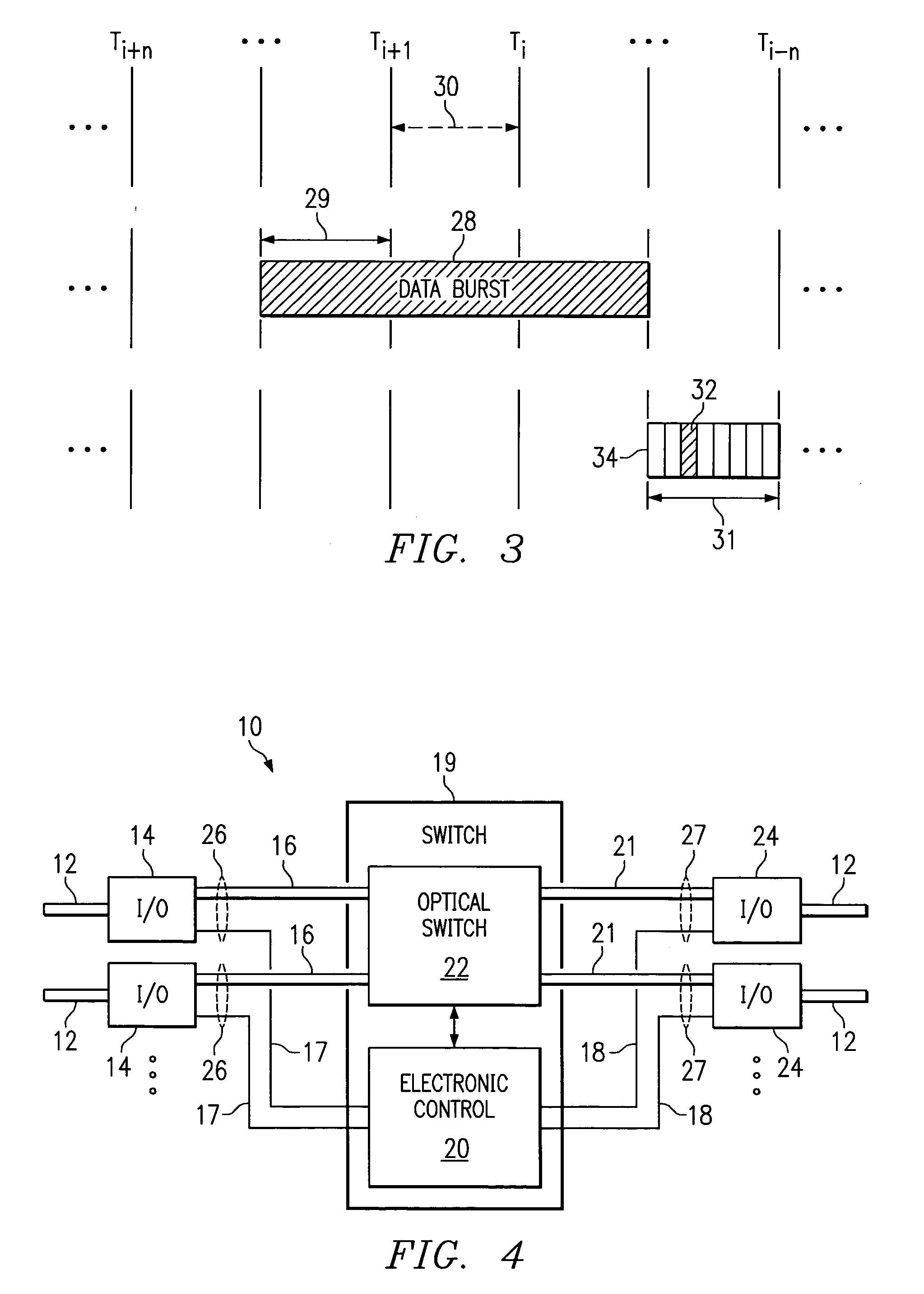
[0050]FIG. 1 illustrates a general block diagram of an optical switched network 4. The optical switched network 4 includes multiple electronic ingress edge routers 6 and multiple egress edge routers 8. The ingress edge routers 6 and egress edge routers 8 are coupled to multiple core routers 10. The connections between ingress edge routers 6, egress edge routers 8 and core routers 10 are made using optical links 12. Each optical fiber can carry multiple channels of optical data.

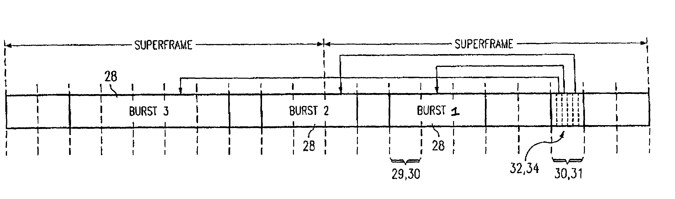
[0051]In operation, a data burst (or simply “burst”) of optical data is the basic data block to be transferred through the network 4. Ingress edge routers and egress edge routers are responsible for burst assembly and disassembly functions, and serve as legacy interfaces between the optical switched network 4 and conventional electronic routers.

[0052]As in...


PUM


Abstract

A network (4) includes optical routers (19), which route information in fibers (10). Each fiber carries a plurality of data channels (16), carrying data in data bursts (28) and a control channel, carrying control information in burst header packets (32). A burst header packet includes routing information for an associated data burst (28) and precedes its associated data burst. Information on the data channels and control channel is organized in synchronized slots. Multiple burst header packets occupy portions of a slot, referred to as micro-slots. When the burst header packets are received, an egress processor (52) schedules the routing of their associated bursts. The egress processor (52) determines a time at which a data burst can be scheduled for passing through an optical matrix (40) to the desired output channel group (the burst can be delayed via fiber delay lines (46) if necessary).

Description

CROSS-REFERENCE TO RELATED APPLICATIONS[0001]This application claims the benefit of the filing date of copending provisional application U.S. Ser. No. 60 / 257,825, filed Dec. 22, 2000, entitled “Method and Apparatus for Synchronized Slotted Optical Burst Switching” to Liu.[0002]This application is related to U.S. Ser. No. 09 / 569,488 filed May 11, 2000, now U.S. Pat. No. 6,819,970, entitled, “All-Optical Networking Optical Fiber Line Delay Buffering Apparatus and Method”, which claims the benefit of U.S. Ser. No. 60 / 163,217 filed Nov. 2, 1999, entitled, “All-Optical Networking Optical Fiber Line Delay Buffering Apparatus and Method” and is hereby fully incorporated by reference. This application is also related to U.S. Ser. No. 09 / 409,573 filed Sep. 30, 1999, now U.S. Pat. No. 6,721,315, entitled, Control Architecture in Optical Burst-Switched Networks” and is hereby incorporated by reference. This application is further related to U.S. Ser. No. 09 / 689,584, filed Oct. 12, 2000, now U....

Claims


Application Information

Patent Timeline
IPC IPC(8): H04J4/00H04L12/43H04L12/28H04L12/427H04J14/02H04Q11/00
CPCH04J14/0227H04Q11/0066H04J14/0241H04J14/0284H04Q2011/0033H04Q2011/0039H04Q2011/005H04Q2011/0064
Inventor LIU, HEYUN H.
Owner RPX CORP
Why Eureka
Try Eureka