Heating flange for preheating air in an intake line of an internal combustion engine

a technology of preheating device and intake line, which is applied in the direction of engine components, mechanical equipment, fuel treatment, etc., can solve the problems of comparatively high technical expenditure and preheating device, and achieve the effects of improving robustness, facilitating mounting and fast heating of intake air

Inactive Publication Date: 2005-11-15
DAVID & BAADER DBK GMBH
View PDF68 Cites 28 Cited by
  • Summary
  • Abstract
  • Description
  • Claims
  • Application Information

AI Technical Summary

Benefits of technology

[0008]An improved heating flange, in particular for preheating air in an intake line leading to an internal combustion engine, is provided which guarantees fast heating of the intake air as well as increased robustness and simplified mounting.

Problems solved by technology

These systems are, however, disadvantageous insofar as the content of the oxygen required for the future combustion of the fuel is reduced and that, in addition, the technical expenditure is comparatively high.
This preheating device is, however, problematic insofar as, due to the high currents flowing (up to 400 ampere and more), the heating flange has to satisfy very special requirements with respect to current endurance, temperature resistance and mechanical stability.

Method used


Image

  • Heating flange for preheating air in an intake line of an internal combustion engine
  • Heating flange for preheating air in an intake line of an internal combustion engine
  • Heating flange for preheating air in an intake line of an internal combustion engine

Examples


Embodiment Construction

[0023]The illustrated embodiments of the present invention will be described with reference to the figure drawings wherein like elements and structures are indicated by like reference numbers.

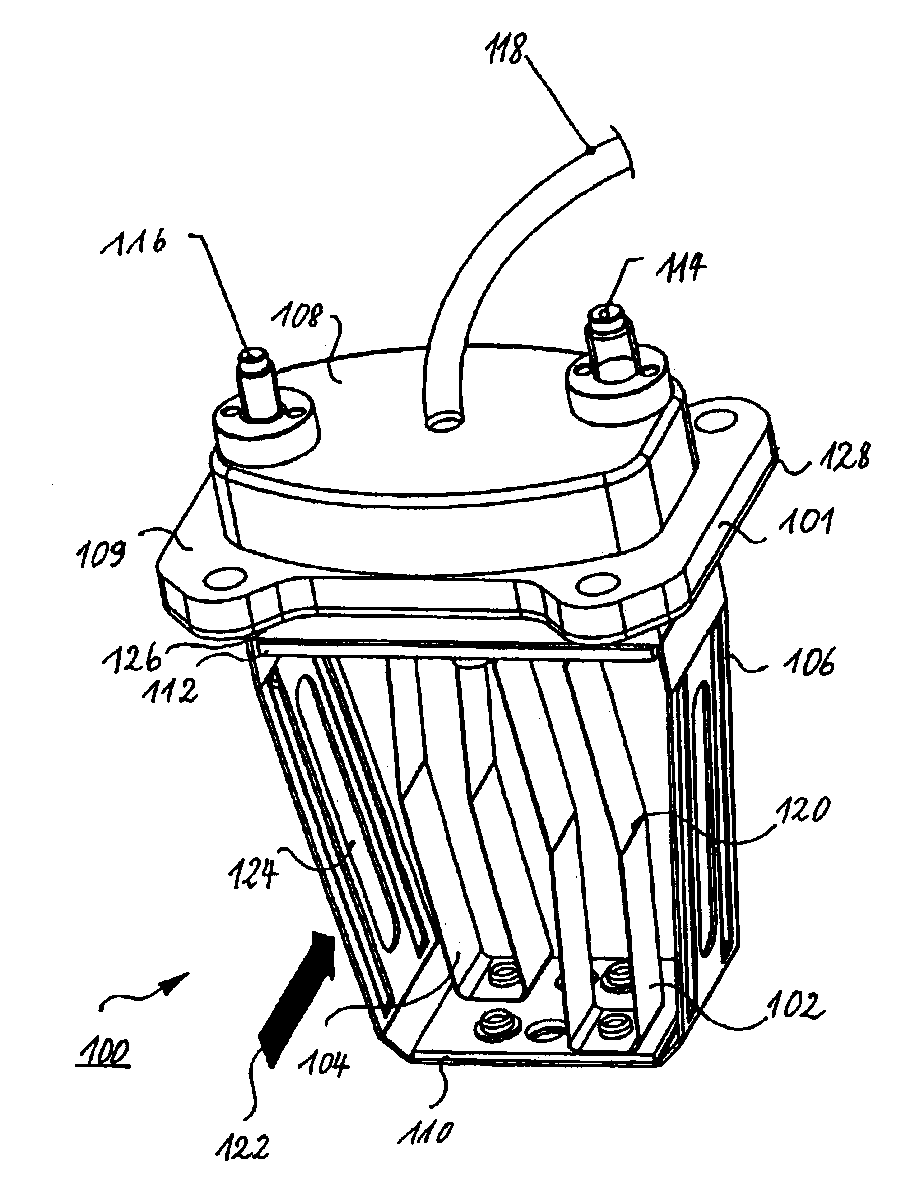
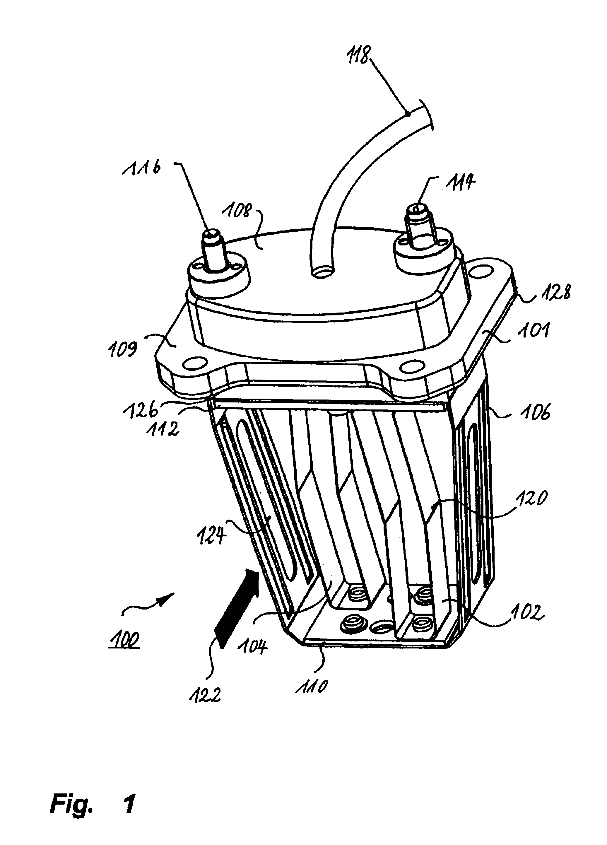
[0024]Referring now to the drawings and in particular to FIG. 1, a perspective representation of a heating flange according to the present invention in accordance with a first advantageous embodiment is shown. The heating flange 100 comprises a body 101 which is adapted to be mounted on an intake line in such a way that the two heating elements 102 and 104 are immersed in the air current to be heated, said intake line leading to an internal combustion engine. The heating elements 102, 104 are heated by an electric current flowing through same, whereby the air flowing around said heating elements will be heated.

[0025]In the embodiment shown, each of the two heating elements 102, 104 is defined by a substantially U-shaped meander loop. Such meander heating elements are particularly suitable for h...


PUM


Abstract

The present invention relates to a heating flange, in particular for preheating air in an intake line leading to an internal combustion engine. The heating flange comprises at least one heating element for heating the air flowing past said heating element, and a body for mechanically holding and electrically contacting said heating element. For providing an improved heating flange, which is used in particular for preheating air in an intake line leading to an internal combustion engine and which guarantees fast heating of the intake air as well as increased robustness and simplified mounting, said body comprises a fastening bow having a substantially U-shaped cross-section, and said heating element comprises at least one substantially U-shaped meander loop which is fixedly connected to the base of said fastening bow.

Description

BACKGROUND OF THE INVENTION[0001]1. Field of the Invention[0002]The present invention generally relates to a heating flange and more specifically to a heating flange for preheating air in an intake line leading to an internal combustion engine.[0003]2. Description of the Related Art[0004]Presently, for instance in diesel engines, the use of pre-swirl chambers is normally dispensed with to a large extent, and the preheating time can be reduced markedly by means of direct fuel injection under high pressure. In the case of lorries, preheating is normally dispensed with completely, and the temperature required for igniting the fuel is here achieved by strong air compression. This technique depends, however, to a high degree on the temperature and the density of the combustion air taken in. At low temperatures, the electric starter must rotate the engine until a temperature rise has taken place in the combustion chambers due to a plurality of compression processes and until ignition of t...

Claims


Application Information

Patent Timeline
Patent Type & Authority Patents(United States)
IPC IPC(8): F02M31/13F02M31/02
CPCF02M31/13Y02T10/126Y02T10/12
Inventor GSCHWIND, THOMASWEBER, THOMASPRONER, MATHIASBAUER, HANS-PETER
Owner DAVID & BAADER DBK GMBH
Why Eureka
Try Eureka