Ultrasonic clutch

a technology of ultrasonic clutch and engaging device, which is applied in the direction of mechanical actuated clutches, magnetically actuated clutches, generators/motors, etc., can solve the problems of high cost of manufacturing conventional clutches, easy damage to the and complex structure of conventional clutches with engaging devices. , to achieve the effect of simplifying the structur

Inactive Publication Date: 2005-11-15
NATIONAL UNITED UNIVERSITY
View PDF11 Cites 10 Cited by
  • Summary
  • Abstract
  • Description
  • Claims
  • Application Information

AI Technical Summary

Problems solved by technology

However, the structure of the conventional clutch with an engaging device is complex, and the cost for manufacturing the conventional clutch is high.
Additionally, the impact will occur when the engaging device of the conventional clutch is engaged or disengaged, whereby the structure of the conventional clutch is easily damaged and the difference of rotation speed between the driving device and the loading must be limited to a small range.
However, the structure of the conventional clutch with the electrical control device is also complex, and the electrical control device is easily interfered with by electromagnetic waves.

Method used


Image

  • Ultrasonic clutch
  • Ultrasonic clutch
  • Ultrasonic clutch

Examples


Embodiment Construction

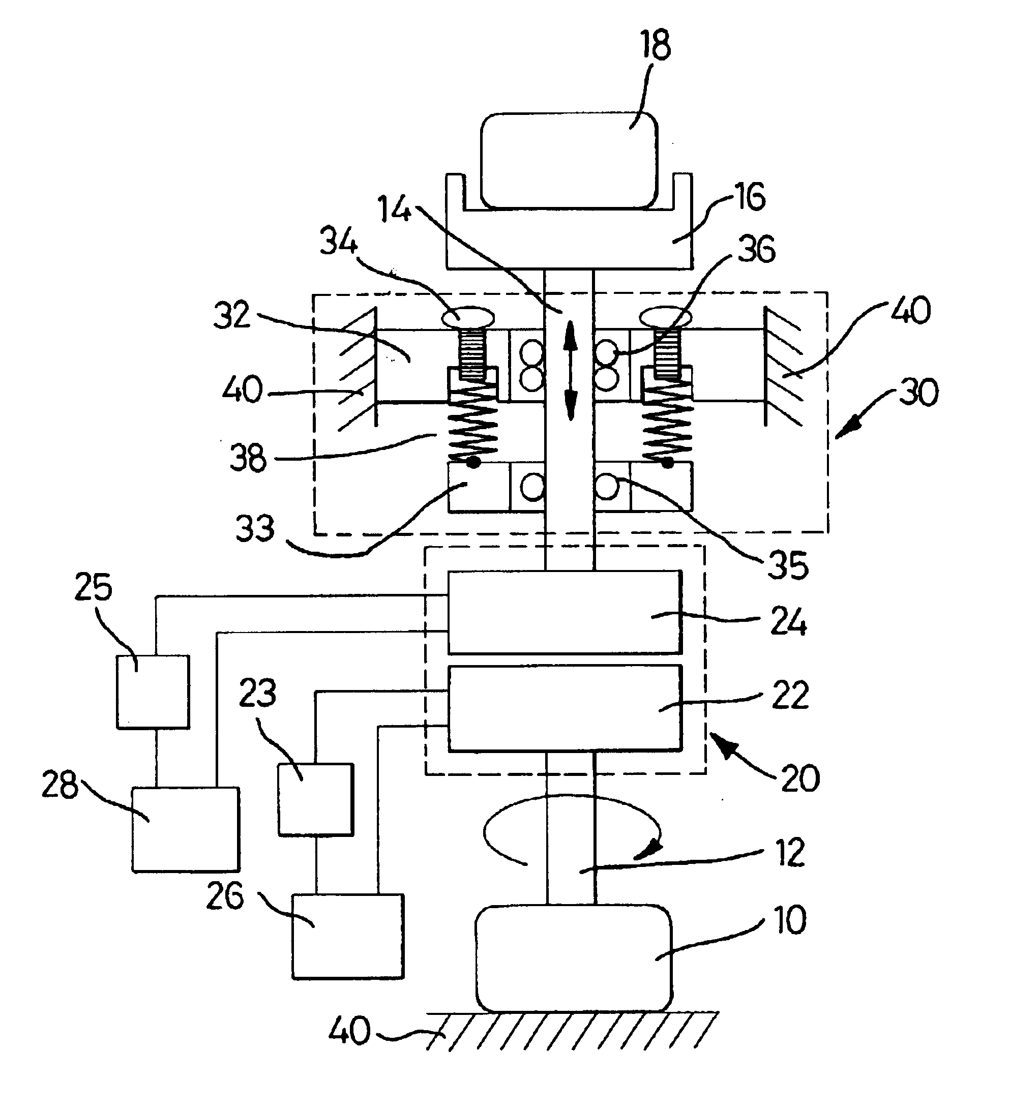
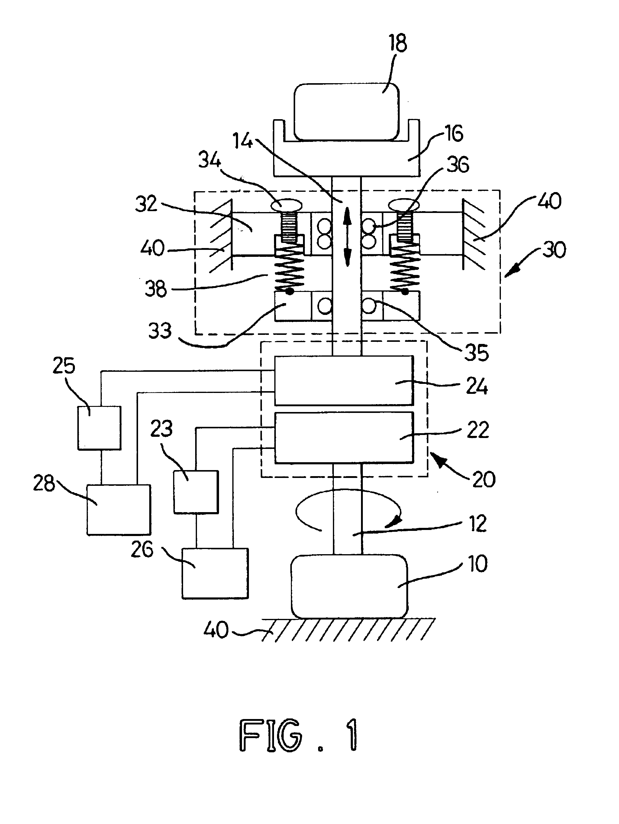
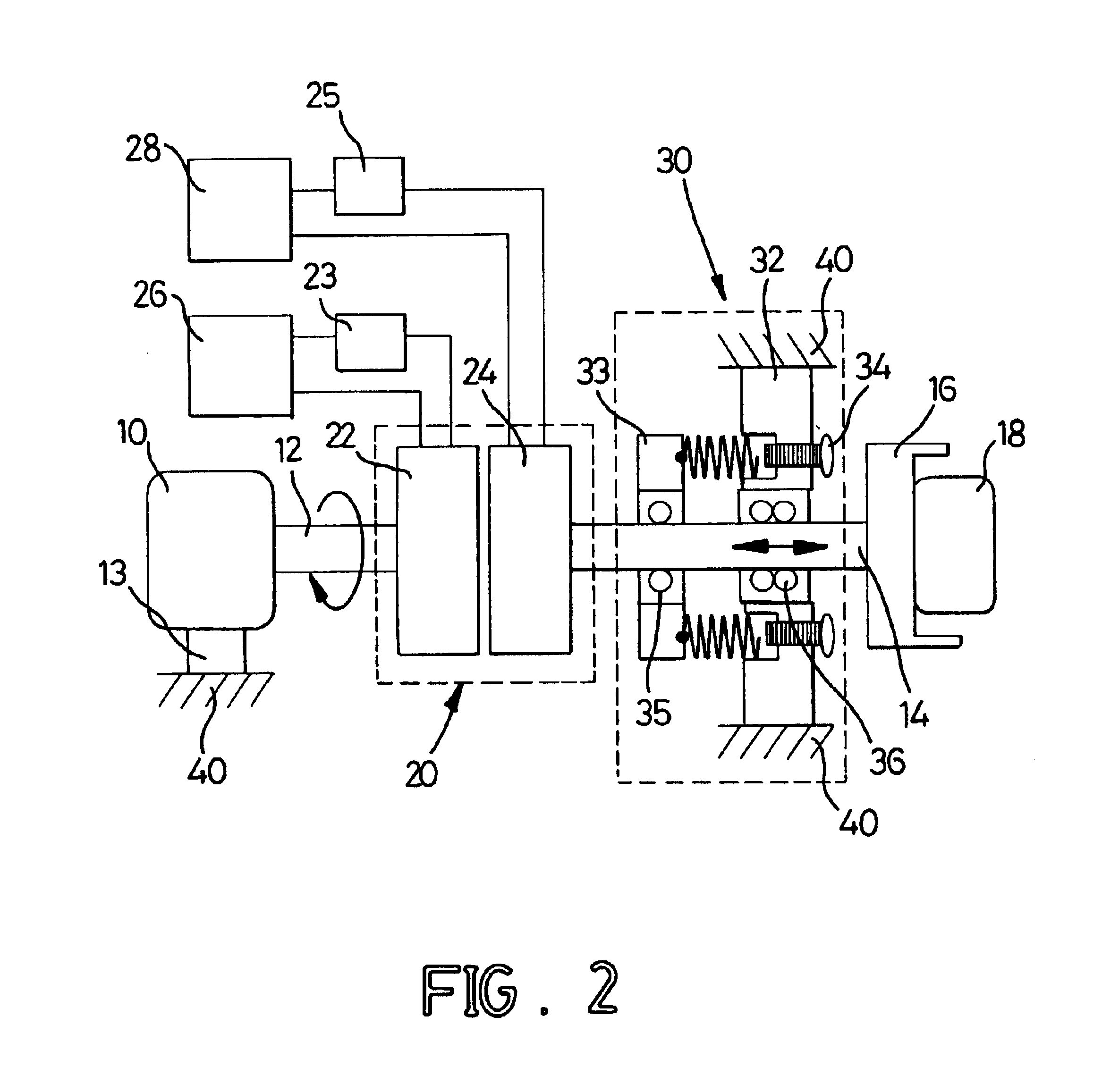
[0030]FIG. 1 is a schematic diagram of a vertical driving-loading system with an ultrasonic clutch. FIG. 2 is a schematic diagram of a horizontal driving-loading system with an ultrasonic clutch. In FIG. 2, a driving device 10 is fixed on a secured base 13. With reference to FIG. 1, a driving-loading system comprises a driving device 10 on a platform 40, a shaft 12 of the driving device 10, a loading 18 on a loading plate 16, an output axle 14 of the loading 18, an ultrasonic clutch 20, and a pre-loaded force regulator 30. The ultrasonic clutch 20 is mounted between the driving device 10 and the loading 18 to control the connection and separation between the two elements through the operation of control switches 23 and 25. An ultrasonic clutch subsystem includes an ultrasonic clutch 20, two alternating current (AC) power sources 26 and 28, and two control switches 23 and 25. Wherein, the ultrasonic clutch 20 in accordance with the present invention comprises a driving element 22 and...


PUM


Abstract

An ultrasonic clutch includes a driving element, a driven element and at least one alternating current (AC) power source. The driving element and the driven element are connected to a shaft of a driving device and an output axle of a loading, respectively. At least one of the driving element and the driven element is a piezoelectric device. When at least one of the driving element and the driven element is electrically connected to an AC power source, the near-field acoustic levitation, generated from the flexural vibration of the piezoelectric resonator above the piezoelectric resonator, occurs to push the driven element away from the driving element. Thus, the output shaft of the loading does not rotate with the axle of the driving device.

Description

BACKGROUND OF THE INVENTION[0001]1. Field of the Invention[0002]The present invention relates to an ultrasonic clutch, and more particularly to an ultrasonic clutch with a piezoelectric device to make a driven element move far away from a driving element when an alternating current (AC) electrical power is applied to the piezoelectric device.[0003]2. Description of Related Art[0004]A clutch is mounted between a driving device and a loading to make the two elements combine with each other or to separate the two elements when the clutch is actuated. A conventional clutch in accordance with the prior art substantially comprises a driving element connected to the driving device, and a driven element connected to the loading. When the driven element is attached to the driving element, the loading is connected to the driving device and actuated by the driving device.[0005]A type of the conventional clutch comprises an engaging device arranged between the driving element and the driven ele...

Claims


Application Information

Patent Timeline
Patent Type & Authority Patents(United States)
IPC IPC(8): F16D27/00H02N2/16
CPCF16D28/00
Inventor CHANG, KUO-TSIOUYANG, MIN-SHEN
Owner NATIONAL UNITED UNIVERSITY
Why Eureka
Try Eureka