
Laryngoscope blade and handle

Inactive Publication Date: 2005-11-15
VYGON
View PDF4 Cites 12 Cited by
  • Summary
  • Abstract
  • Description
  • Claims
  • Application Information

AI Technical Summary

Benefits of technology

[0008]An object of the present invention is to provide a laryngoscope of design that is much less expensive, and compatible for use with single-use blades.
[0009]The invention seeks to ensure that the blade is locked without compromising the cost of manufacturing the blade and without repeated use of the handle compromising the effectiveness of locking.
[0012]This design thus simplifies the handle of the blade by providing the abutment for coming into contact with the flexible wall of the tab in the form of a simple stationary bar parallel to the bar which is surrounded by the hook.

Problems solved by technology

Since the handle is for repeated used, there exists a risk of fatigue in the spring blade, causing it to become less effective in locking the blade.

Method used


Image

  • Laryngoscope blade and handle
  • Laryngoscope blade and handle
  • Laryngoscope blade and handle

Examples


Embodiment Construction

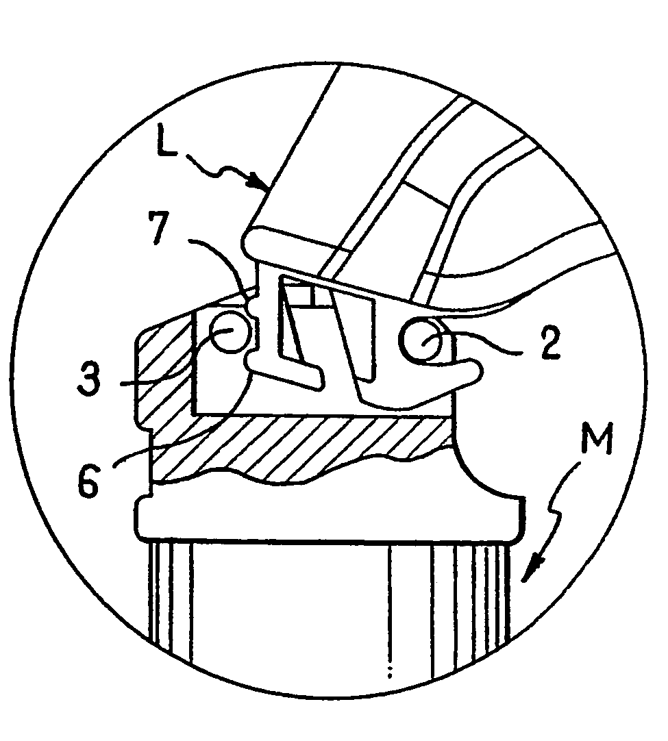
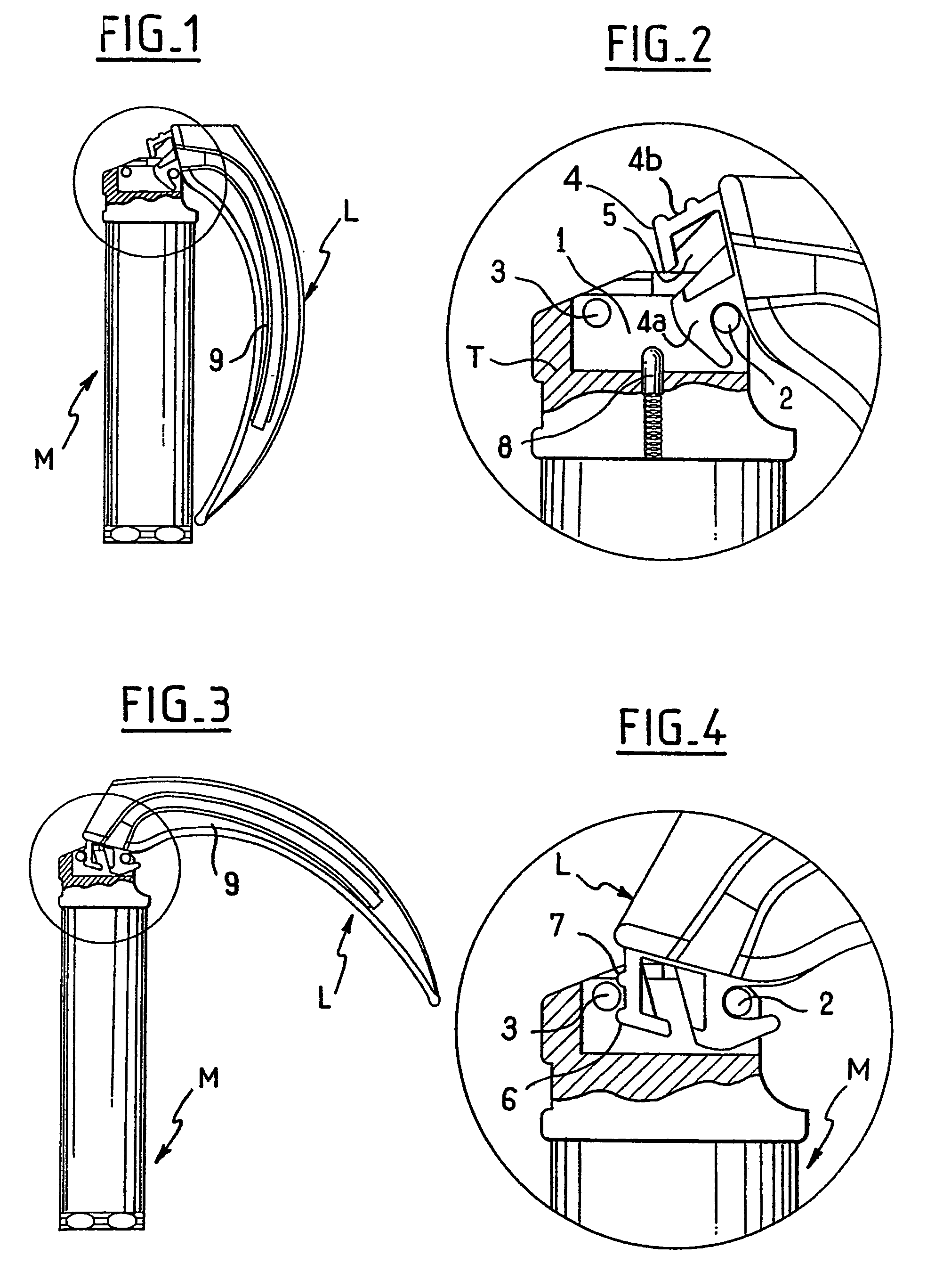
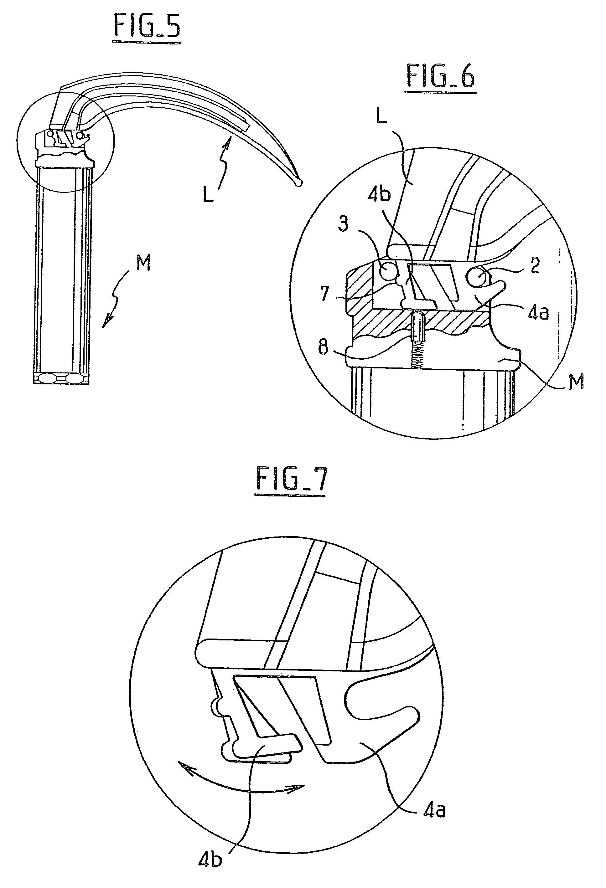
[0020]The figures show the blade L and the handle M of an embodiment of a laryngoscope in accordance with the invention.

[0021]The handle (M) is a hollow metal cylinder suitable for holding in the hand and presenting an end closed by a head T screwed onto the cylinder so as to define a cavity (1) that is open to the outside and in which there are to be found a first bar (2) and a second bar (3) which are rigid and stationary and disposed parallel to each other across the cavity.

[0022]The blade (L) is made of synthetic resin and is shaped so as to be suitable for being inserted in the mouth in order to press the tongue down against the lower jaw and to raise the epiglottis, and it presents a tab (4) at one end constituted by a hook (4a) and by a flexible ribbed wall (4b) separated from the hook by an empty gap (5). The ribbed wall presents two parallel ribs (6, 7).

[0023]The tab is dimensioned so as to be capable of being forced into the cavity in the head of the handle with the hook e...


PUM


Abstract

The tab on the blade of a laryngoscope presents a flexible hook and an elastically-flexible wall for being inclined towards the hook when it engages a stationary abutment situated on the handle of the laryngoscope while the hook is engaged on a bar present in a cavity of the laryngoscope.

Description

BACKGROUND OF THE INVENTION[0001]The invention relates to laryngoscopes of the type comprising a non-metallic blade for single or little-repeated use and a handle for intensive use, the blade and the handle being provided with respective means that co-operate to enable the blade to be assembled in detachable manner on the handle in at least one predefined position.[0002]The means for assembling the blade on the handle comprise engagement means which enable the blade to be engaged on the handle, and spring effect locking means which act to hold the blade in the selected position but which can be made inactive by appropriate manipulation of the blade in order to be able to separate the blade from the handle after use.[0003]Publication EP 0 169 497 describes an embodiment in which:[0004]the engagement means comprise both a cavity situated in one end of the handle, which cavity is open to the outside-and contains a bar placed across the cavity, and a hook formed on a tab at one end of t...

Claims


Application Information

Patent Timeline
IPC IPC(8): A61B1/267A61B17/24A61B1/273
CPCA61B1/267
Inventor DALLE, VALERYEUDES, YVANTRELLU, ERIC
Owner VYGON
Learn More