Eureka AIR delivers breakthrough ideas for toughest innovation challenges, trusted by R&D personnel around the world.

Interrupting apparatus having operations counter and methods of forming and using same

a technology of interrupting apparatus and counter, which is applied in the direction of air-breaking switch details, hot sticks switches, high-tension/heavy-dress switches, etc., can solve the problems of difficult to accurately keep track of the number of operations performed by each interrupting apparatus, damage to any component, and type of injury, so as to facilitate maintenance, improve durability, and reduce the chance of counter damage

Inactive Publication Date: 2005-11-15
UTILITY SOLUTIONS
View PDF10 Cites 1 Cited by
  • Summary
  • Abstract
  • Description
  • Claims
  • Application Information

AI Technical Summary

Benefits of technology

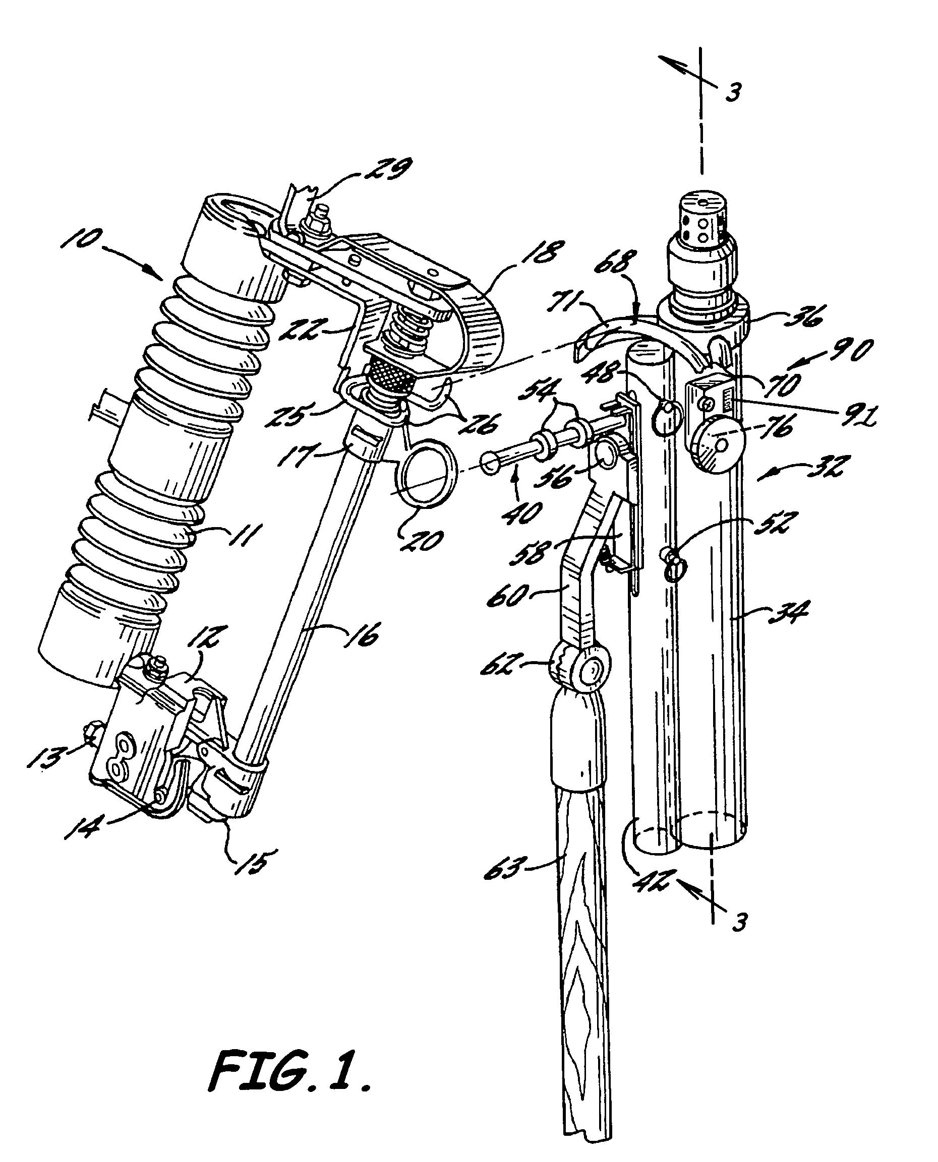
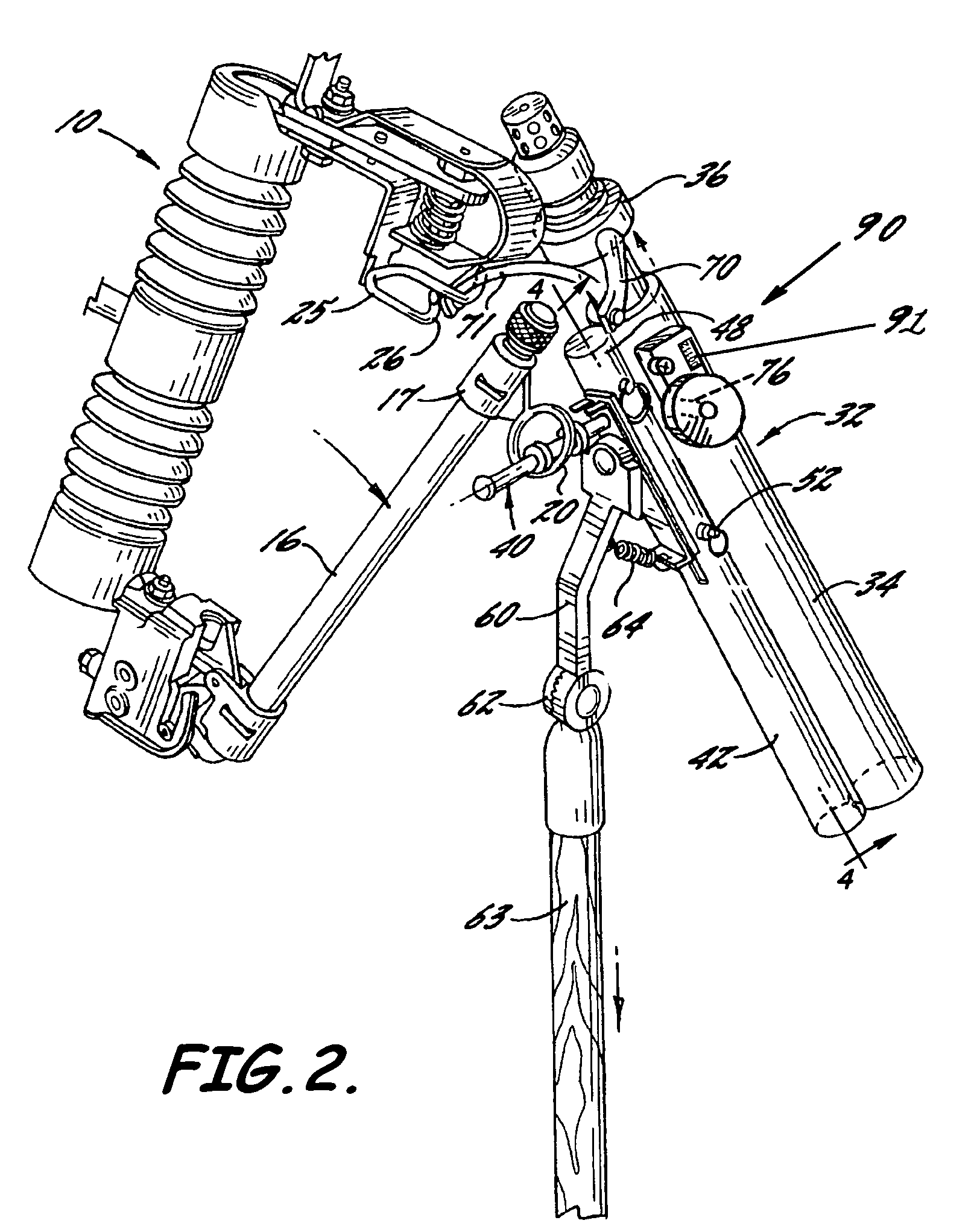
[0011]In view of the foregoing, embodiments of the present invention advantageously provide an apparatus and methods related to formation and use of a circuit interrupting apparatus that provide the user the ability to count the number of circuit interruption events performed on circuit isolating devices. Advantageously, embodiments of the present invention also provide a circuit interrupting apparatus which includes a counter that can count the number of operations performed by each circuit interrupting apparatus that does not require direct interface with shunt interrupting circuit components. Advantageously, embodiments of the present invention also provides a counter and methods that can record total operation counts along with operation counts related to various categories of amperage interrupted by a circuit interrupting apparatus. Advantageously, an embodiment of the present invention provides an operation counter that can be easily and inexpensively retrofitted to existing circuit interrupting apparatus.
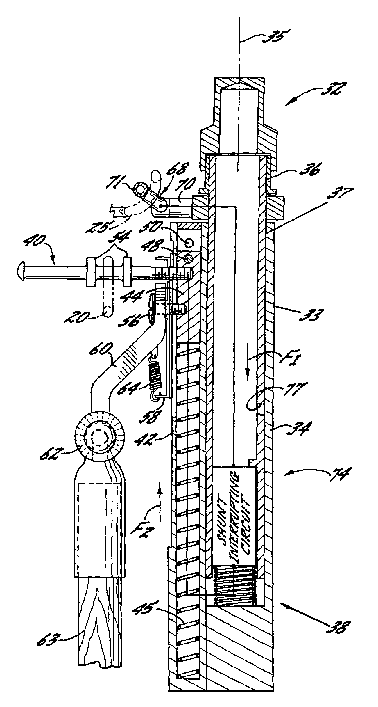
[0014]The portable circuit interrupting apparatus also includes a reset plunger assembly, which includes a reset plunger, connected to a medial portion of the main housing body. The reset plunger is adapted to have at least portions thereof extend through a reset plunger opening positioned in the medial portion of the main sleeve body when in a non-reset and biased inward lock position to releasably lock the sleeve in the extended position. This allows the interrupting apparatus to obtain and maintain an electrical clearance between the ring engaging terminal and the hook engaging terminal when the ring engaging terminal and the hook engaging terminal engage a circuit isolating device and when the main sleeve body is positioned in the extended position. The reset plunger is also adapted to reset outwardly in response to outwardly biased pressure by a user and outward pressure from the main sleeve outer surface when the sleeve main body is in an at least partially retracted position.
[0016]The operation counter assembly can also include a selection switch for selecting a plurality of categories of amperage range of values most closely associated with the circuit isolating device. The operation counter can separately record the operation count and associate the operation count with a category selected from the plurality of categories and can track a number of counts associated with each of the plurality of categories and display the number of counts associated with the category so selected. This provides the user the ability to develop maintenance schedules based on actual usage in both quantity and quality.
[0019]A circuit interrupting apparatus according to an embodiment of the present invention advantageously can be used for keeping track of the number of circuit interrupting operations of and thus the number of circuit isolating devices serviced. This can help facilitate maintenance based on the number of raw operations or an itemized account of operations based on the amperage interrupted rather than length of time the interrupting apparatus is in the field. Advantageously, in an embodiment of the present invention the operations counter is not exposed to exhaust gases during use and, due to the positioning, can be housed in a durable metal housing to improve durability and lessen the chance of damage to the counter. Advantageously, in embodiments of the present invention, an operations counter cannot be reset to provide for a continuous monitoring of the operations performed throughout the life of the interrupting apparatus. Advantageously, in embodiments of the present invention, an operations counter can be positioned to count each time the tool is reset; thus, it never comes in contact with any internal loadbreak mechanisms.

Problems solved by technology

When it is necessary to open the circuit isolating device when it is carrying load current, an arc is drawn between the two conducting parts, which is likely to damage any components which are contacted by the arc.
Also, where other adjacent circuits are involved, there is a risk that the drawn arc may jump to another circuit, causing a fault in the other circuit.
Still further, there is a risk that the drawn arc can jump an operator, causing some type of injury.
It is, however, difficult to accurately keep track of the number of operations performed by each interrupting apparatus.
Applicants have recognized that counters such as that described, however, are prone to excessive wear because part of the counter mechanism is in contact with arc-interrupting components or shunt-interrupting circuits which are subject to the wear and tear or other forms of degradation caused by arcing resulting from the circuit interrupting operation.
Additionally, there are many circuit interrupting apparatus deployed in the field which do not have an operation counter.
Though operator productivity is not a function of the amperage of the circuits repaired by the operator and a rough representation of component fatigue can be deduced from a raw count of the number of operations, high amperage operations cause much more wear and erosion than medium amperage operations which cause more wear and erosion than low amperage operations.

Method used


Image

  • Interrupting apparatus having operations counter and methods of forming and using same
  • Interrupting apparatus having operations counter and methods of forming and using same
  • Interrupting apparatus having operations counter and methods of forming and using same

Examples


Embodiment Construction

[0029]The present invention will now be described more fully hereinafter with reference to the accompanying drawings which illustrate embodiments of the invention. This invention may, however, be embodied in many different forms and should not be construed as limited to the illustrated embodiments set forth herein. Rather, these embodiments are provided so that this disclosure will be thorough and complete, and will fully convey the scope of the invention to those skilled in the art. Like numbers refer to like elements throughout, and the prime notation, if used, indicates similar elements in alternative embodiments.

[0030]As illustrated in FIGS. 1–8, embodiments of the present invention advantageously provide a portable circuit interrupting apparatus 32 for use in association with a utility powerline circuit isolating device to expeditiously open the circuit, typically medium and high-voltage isolating device 10 while it is carrying line current. The circuit interrupting apparatus 3...


PUM


Abstract

A portable circuit interrupting apparatus for use on a circuit isolating device and associated methods of formation and use are provided. The portable circuit interrupting apparatus includes a main housing body and a sleeve coaxially mounted therein. The sleeve is slidable between an extended and retracted position. A shunt circuit segment is connected between ring and hook engaging terminals which engage and form an electrical connection between ring-like and hook-like conducting parts of the circuit isolating device. A shunt circuit segment interrupts the electrical connection in response to movement of the sleeve from the retracted position to the extended position. At least portions of a reset plunger extend inwardly through an opening in a medial portion of the sleeve when in the extended position. An operation counter is connected to and responds to the inward extension of the reset plunger to count a number of circuit interrupting operations.

Description

BACKGROUND OF THE INVENTION[0001]1. Field of the Invention[0002]The present invention relates to a circuit interrupting apparatus and, more particularly, to a circuit interrupting apparatus for medium- and high-voltage circuit isolating devices having operations counters and methods of forming and using such circuit interrupting apparatus associated therewith.[0003]2. Description of the Related Art[0004]Circuit isolating devices such as fuse cutouts, disconnecting switches, and power fuses are adapted to be periodically opened to provide necessary service, such as for fuse replacement or service to power lines. Conventionally, such circuit isolating devices include a ring-like conducting part and a hook-like conducting part which are relatively movable between a contacting position to establish a closed circuit through the device and a separated position to establish an open circuit through the device.[0005]When it is necessary to open the circuit isolating device when it is carryin...

Claims


Application Information

Patent Timeline
Patent Type & Authority Patents(United States)
IPC IPC(8): H01H9/38H01H9/30H01H31/00H01H31/12H01H85/02
CPCH01H31/006H01H85/0208H01H31/127
Inventor FRANKLIN, DAVID A.WOOD, EUGENE H.NOLTE, MICHAEL G.
Owner UTILITY SOLUTIONS
Why Eureka
Eureka Blog
Learn More