Method for operating a wind turbine

a wind turbine and wind power technology, applied in the direction of electric generator control, instruments, heat measurement, etc., can solve the problems of wind turbine not producing electric power, high mechanical load, mechanical stress, and difficulty in maintaining an even heat distribution across the bearing

Active Publication Date: 2017-06-13
SIEMENS GAMESA RENEWABLE ENERGY AS
View PDF14 Cites 0 Cited by
  • Summary
  • Abstract
  • Description
  • Claims
  • Application Information

AI Technical Summary

Benefits of technology

[0027]Therefore, even if the determined temperature difference between the at least two components of the bearing increases above the upper threshold temperature difference, the method according to embodiments of the invention generally, allows for maintaining the production of electric power.
[0028]Consequently, the method according to embodiments of the invention further allows for reducing heat transfer between the components of the bearing which are relatively lower in temperature, i.e. particularly the outer ring, and the generator, which may reduce a given temperature difference between the outer ring and the inner ring originating from a comparatively “cold” outer ring and a comparatively “hot” inner ring. The temperature difference is based on the fact that the outer ring usually has a considerable lower temperature than the inner ring since the outer ring is more exposed to ambient conditions and therefore likely, to be cooled by ambient air.
[0040]By using a respective further threshold temperature difference between the at least two components of the bearing, it may be assured that the temperature difference between respective bearing components is sufficiently below the upper threshold temperature difference so that a cancellation of limitation of the rotational speed of the rotor and / or the at least one wind turbine component and / or a cancellation of limitation of electric power output of the generator will not be conducted too early, i.e. will not be directly subsequently followed by a new limitation.
[0045]According to a further embodiment of the method, emanating from an applied limitation of rotational speed of the rotor and / or the at least one wind turbine component and / or emanating from an applied limitation of electric power output of the generator, operation of the wind turbine is temporarily completely interrupted, if the temperature difference between the at least two components of the bearing continues increasing above the upper threshold temperature difference and particularly, reaches a maximum admissible threshold temperature difference. In such a manner, situations of comparatively high mechanical loads, i.e. particularly mechanical stresses, due to comparatively large temperature differences within the bearing and therefore, the risk of damages of bearing components or the entire bearing, respectively may be avoided.
[0049]According to a further embodiment of the method, after resuming operation of the wind turbine, operation of the wind turbine is at least temporarily conducted with a limitation of rotational speed of the rotor and / or the at least one wind turbine component to the or a value unlike zero, yet below a wind turbine specific nominal rotational speed of the rotor and / or the at least one wind turbine component and / or with a limitation of electric power output of the generator to the or a value unlike zero, yet below the wind turbine specific nominal electric power output of the generator. In such a manner, aforementioned problems which may occur during a cold start-up of the wind turbine may be avoided or at least reduced.

Problems solved by technology

It is difficult to maintain an even heat distribution across the bearing, i.e. particularly across respective outer and inner rings.
Especially, during initial operation of the wind turbine, i.e. during so called cold start-up situations, the outer and inner rings of the bearing can experience comparatively large temperature differences or gradients, respectively resulting in comparatively high mechanical loads, particularly mechanical stresses, within the bearing.
In this case, the wind turbine does not produce electric power.
Since respective temperature differences within the bearing regularly occur, this approach typically results in often shut-downs of the wind turbine which is an improvable situation in regard of the general aim of continuously operating of the wind turbine and continuously producing electric power.
Of course, it is also possible that an applied limitation of rotational speed of the rotor and / or the at least one wind turbine component and / or an applied limitation of electric power output of the generator is manually cancelled by a user.

Method used


Image

  • Method for operating a wind turbine
  • Method for operating a wind turbine
  • Method for operating a wind turbine

Examples


Embodiment Construction

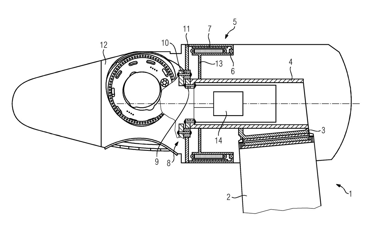
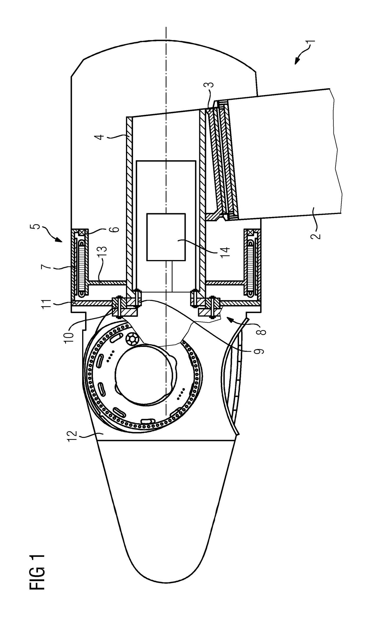
[0066]FIG. 1 shows a principle drawing of a wind turbine 1 according to an exemplary embodiment of the invention. The wind turbine 1 is a direct drive wind turbine.

[0067]The wind turbine 1 comprises a tower construction 2 which is fixed to the ground. A tower connector 3 is attached to the free ending of the tower construction 2. The tower connector 3 supports a main shaft 4 of the wind turbine 1.

[0068]The wind turbine 1 further comprises a generator 5. The generator 5 comprises a stator 6 and a rotor 7. The rotor 7 is rotatably supported relative to the stator 6 by means of a bearing 8. The bearing 8 may be denoted as main bearing of the wind turbine 1. The bearing 8 comprises an inner ring 9 and an outer ring 10.

[0069]The inner ring 9 is supported on the main shaft 4 in torque-proof manner. The outer ring 10 is connected to the rotor yoke 11. The rotor yoke 11 supports a rotor hub 12 having a number of rotor blades (not shown) attached thereto. The rotor yoke 11 also supports the ...


PUM

PropertyMeasurementUnit
timeaaaaaaaaaa
timeaaaaaaaaaa
timeaaaaaaaaaa

Abstract

A method for operating a direct drive wind turbine including determining a temperature difference between at least two components of a bearing, comparing the temperature information with an upper threshold temperature difference between the at least two components of the bearing, limiting rotational speed of a rotor and / or an at least one rotatably supported wind turbine component coupled to the rotor to a value unlike zero yet, below a wind turbine specific nominal rotational speed of the rotor and / or below the wind turbine specific nominal rotational speed of the at least one rotatably supported wind turbine component coupled to the rotor and / or limiting electric power output of the generator to a value unlike zero yet, below a wind turbine specific nominal electric power output of the generator, if the temperature difference between the at least two components of the bearing increases above the upper threshold temperature difference, is provided.

Description

CROSS REFERENCE TO RELATED APPLICATIONS[0001]This application claims priority European Application No. EP 14169669.0, having a filing date of May 23, 2014, the entire contents of which are hereby incorporated by reference.FIELD OF TECHNOLOGY[0002]The following relates to a method for operating a wind turbine, particularly a direct drive wind turbine, the wind turbine comprising a generator comprising a stator and a rotor, with the rotor being rotatably supported relative to the stator by means of at least one bearing, and a control means adapted to control rotational speed of the rotor and / or at least one rotatably supported wind turbine component coupled to the rotor and / or adapted to control electric power output of the generator.BACKGROUND[0003]It is known that bearings rotatably supporting a rotor of a generator of a wind turbine relative to the stator of the generator of the wind turbine heat up during operation of the wind turbine. It is difficult to maintain an even heat dist...

Claims


Application Information

Patent Timeline
Patent Type & Authority Patents(United States)
IPC IPC(8): F03D9/00H02P9/04F03D9/25F03D17/00F16C19/52G01K13/00F03D7/02F03D1/00H02K7/08H02K9/02H02K9/00H02K7/18
CPCF03D7/0276F03D1/00F03D7/028F03D9/25F03D17/00F16C19/525G01K13/00H02K7/083H02K7/1807H02K9/005H02K9/02F05B2270/101F16C2233/00F16C2360/31Y02E10/722Y02E10/723F05B2270/303Y02E10/72F03D80/60H02K9/00
Inventor HAWKINS, SAMUEL H.
Owner SIEMENS GAMESA RENEWABLE ENERGY AS
Why Eureka
Try Eureka