Removable wound stator for integrated motor/compressor

A stator and motor technology, applied in the field of supercharged gas cooling motors

Inactive Publication Date: 2014-03-26
GENERAL ELECTRIC CO
View PDF8 Cites 0 Cited by
  • Summary
  • Abstract
  • Description
  • Claims
  • Application Information

AI Technical Summary

Problems solved by technology

Also this arrangement does not provide effective tolerance for the relative thermal expansion that occurs in the charge gas cooled motor assembly

Method used


Image

  • Removable wound stator for integrated motor/compressor
  • Removable wound stator for integrated motor/compressor
  • Removable wound stator for integrated motor/compressor

Examples


Embodiment Construction

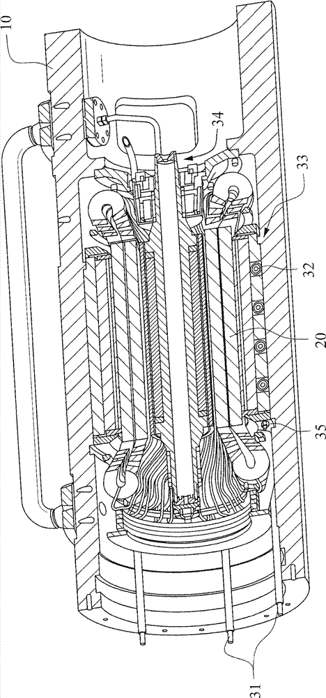
[0044] figure 1 An exemplary embodiment of a charge gas cooled integrated motor-compressor unit is depicted. exist figure 1 , the pressure vessel is shown at 10 to include therein the stator core 20 (in figure 2 shown in ). Pressure vessel 10 includes inlets, outlets, liners, plates and connections for necessary inputs and connections include: stator leads 11; stator gauges 12; gas inlet 13; gas outlet 14; and access plate 15 (cover plate not shown out).

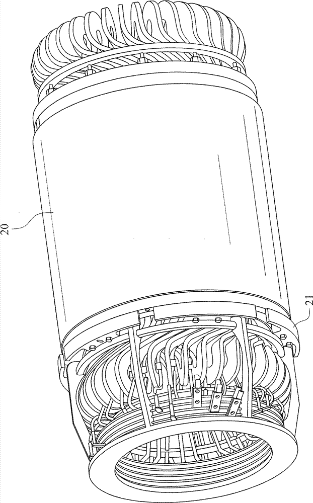
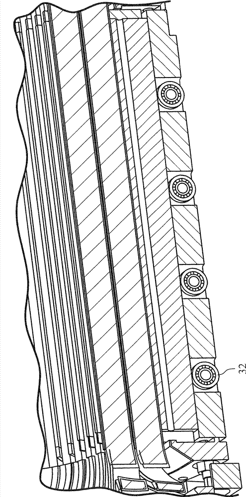
[0045] figure 2 A wound stator core 20 fitted with an axial holding device 21 is shown. As will be described in more detail below, the axial retention means 21 maintains the axial position of the stator core within the pressure vessel during transport and during operating conditions. image 3 The assembly of the stator core 20 within the pressure vessel 10 is shown. Positioning of the stator core 20 within the pressure vessel 10 is facilitated by means of the tool 31 via the rollers 32 . A shoulder 33 is formed in ...


PUM


Abstract

The invention relates to a removable wound stator for an integrated motor / compressor, specifically to a pressurized gas cooled high speed motor which includes a wound stator and rotor assembly disposed within a pressure vessel such that the stator and rotor assembly can be removed without disconnecting the high pressure lines to the pressure vessel. The stator has a spring loaded axial retention mechanism that cooperates with a concentric groove in the pressure vessel for maintaining the stator and rotor assembly fixedly in place in the pressure vessel during transport and operation of the motor. A shoulder formed in the pressure vessel is used to axially position the stator assembly within the pressure vessel. A key if provided for angularly and fixedly positioning the stator within the pressure vessel.

Description

technical field [0001] The present invention relates to charge gas cooled motors for direct drive centrifugal compressors, and more particularly to wound stators designed for such motors, which are detachable from the motor housing (pressure vessel). The invention also includes a stator arrangement that facilitates simultaneous disassembly of the stator and rotor. Background technique [0002] For conventional motor designs, removable stators have been proposed. For example, it is known to axially position a removable stator using a chamfered centering ring and pressure ring provided in the stator and sandwiched between mating chamfered shoulders provided in the motor housing. In addition to requiring accurate centering, this arrangement does not provide significant tolerance for the relative thermal expansion that occurs in the charge gas cooled motor assembly. [0003] It has also been proposed to position the detachable stator axially and use wave springs to angularly a...

Claims


Application Information

Patent Timeline
Patent Type & Authority Applications(China)
IPC IPC(8): H02K1/18
CPCH02K9/08H02K5/04H02K15/0006H02K1/187H02K15/00H02K15/16
Inventor M.J.德布洛克G.T.C.惠勒N.普特纳
Owner GENERAL ELECTRIC CO
Why Eureka
Try Eureka