Microscopy laboratory system

a laboratory system and microscope technology, applied in the field of instruction settings, can solve the problems of inefficiency of the system, the instructor cannot see what the students are viewing through their microscope, and the instructor has no means to annotate an image from a student's microscop

Inactive Publication Date: 2005-11-15
LEICA MICROSYSTEMS CMS GMBH
View PDF10 Cites 7 Cited by
  • Summary
  • Abstract
  • Description
  • Claims
  • Application Information

AI Technical Summary

Benefits of technology

[0004]Therefore, it is an object of the present invention to provide an improved microscopy laboratory system that allows an instr

Problems solved by technology

A drawback of this system is that the instructor cannot see what the students are viewing through their own microscopes.
Clearly, this type of system is inefficient because the instructor must spend time checking the stude

Method used


Image

  • Microscopy laboratory system
  • Microscopy laboratory system
  • Microscopy laboratory system

Examples


Embodiment Construction

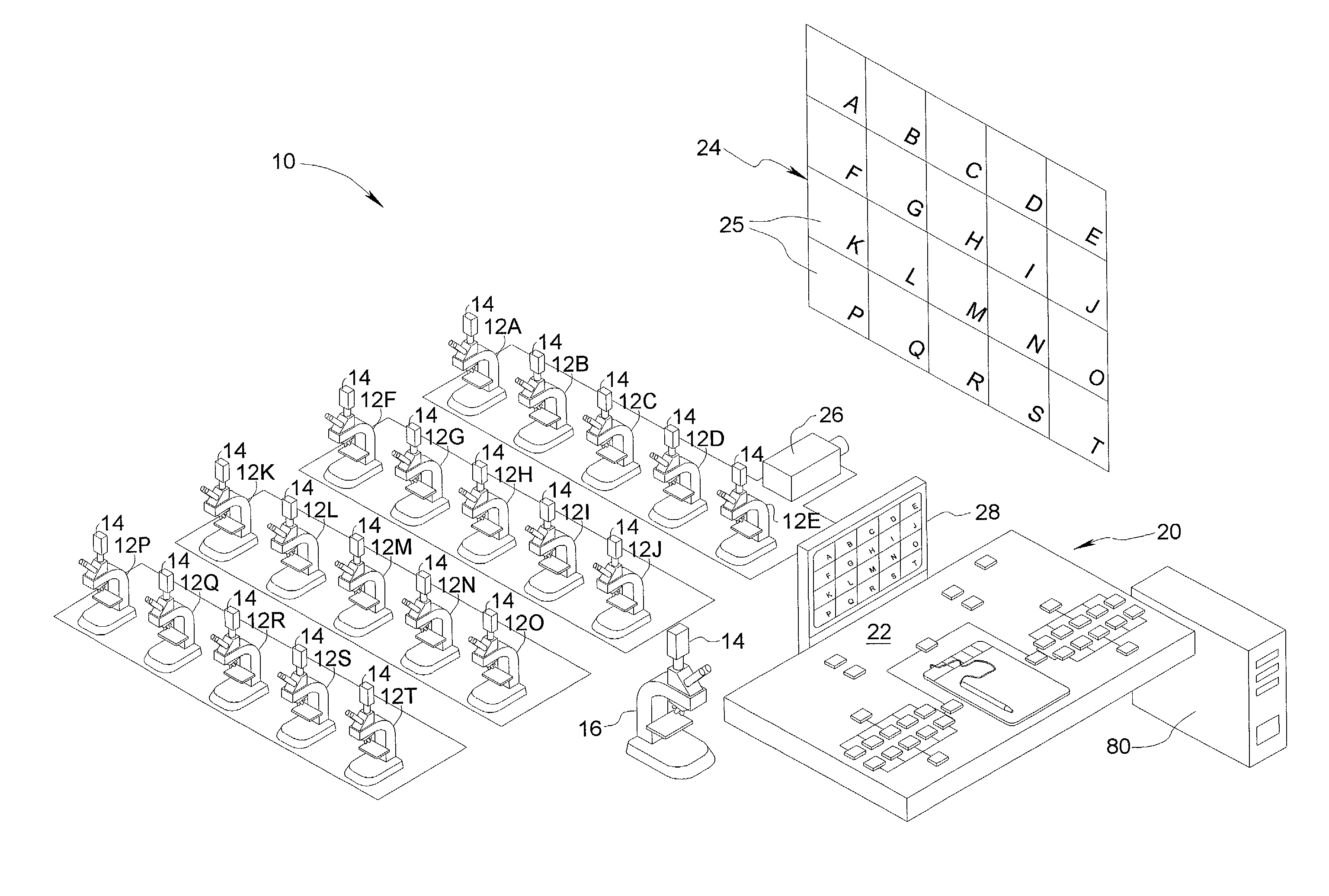
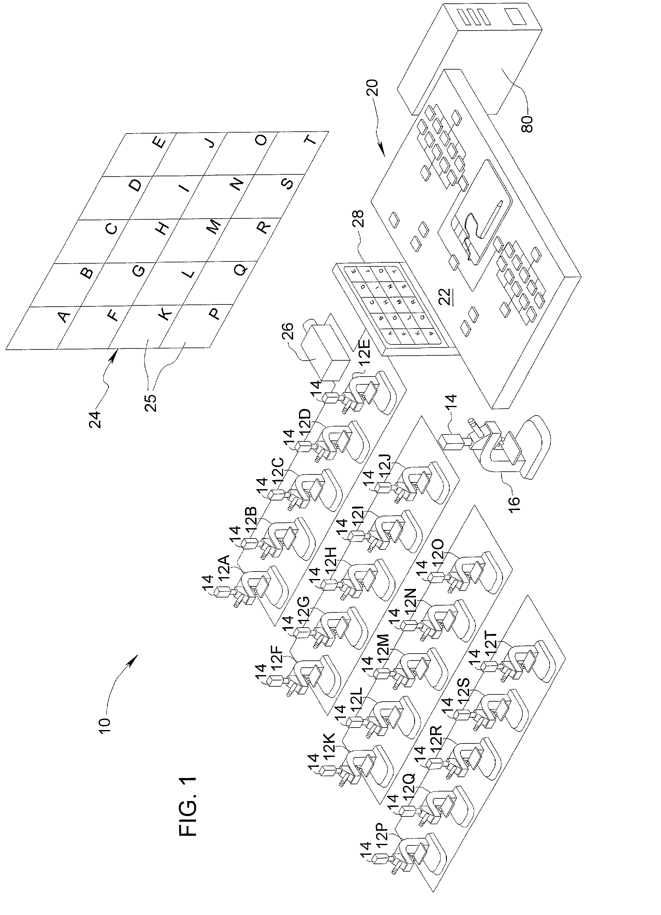
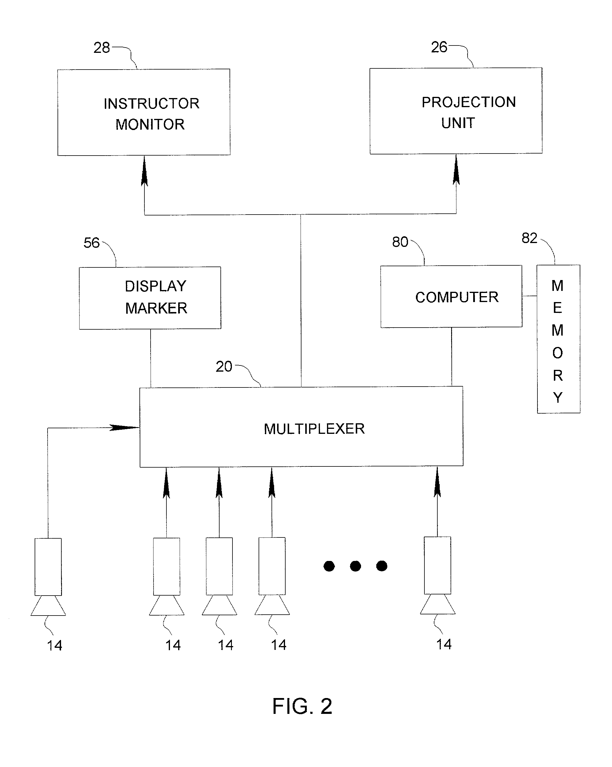
[0016]Referring initially to FIGS. 1 and 2 of the drawings, a microscopy laboratory system formed in accordance with a first embodiment of the present invention is generally identified by reference numeral 10. Microscopy laboratory system 10 comprises a plurality of student microscopes 12A–12T each equipped with a video camera 14 for generating an image signal representing a student view image of at least a portion of the field of view of the corresponding student microscope, and an instructor microscope 16 likewise equipped with a camera 14 for generating an image signal representing an instructor view image of at least a portion of the field of view of instructor microscope 16. Cameras 14 are preferably video cameras that are either retro-fitted to or integrated with the microscope through a C-mount, a trinocular viewing body attachment, or an integrated video module inserted between the microscope stand and the binocular tube of the microscope. By way of non-limiting example, the...


PUM


Abstract

A microscopy laboratory system for efficient instruction is disclosed. The system comprises a plurality of student microscopes each equipped with a camera for generating an image signal representing a student view image of at least a portion of the field of view of the student microscope, multiplexed control means connected by video cables or wireless technology to the cameras to provide a composite instruction image signal based on student view images from one or more selected microscopes, and a projection unit or other public display for presenting the instruction image to the students in the laboratory. An instructor microscope can also be coupled into the system, and a display image marker is preferably linked to the multiplexed control means for inserting instructor annotations into the displayed instruction image.

Description

CROSS-REFERENCE TO RELATED APPLICATIONS[0001]The instant application is a continuation-in-part of U.S. Ser. No. 09 / 821,578, filed Mar. 29, 2001 now U.S. Pat. No. 6,900,776.BACKGROUND OF THE INVENTION[0002]The present invention relates generally to instructional settings wherein participants view specimens through respective microscopes, and more particularly to a microscopy laboratory system wherein an instructor and students can view an overall instructional image that selectively includes images from the field of view of one, some, or all of the microscopes in the laboratory.[0003]Microscopy laboratories at universities, teaching hospitals, etc. are known to include a television monitor or projection unit that receives an image signal from a camera mounted on the instructor's microscope, such as by a C-mount, trinocular viewing body, video module, or the like. In this way, each student in the laboratory can view an image that serves as a model to help him or her position a like sp...

Claims


Application Information

Patent Timeline
IPC IPC(8): G02B21/36G09B19/00G09B23/00G09B5/12G09B5/00G09B5/08G09B23/22G09B23/24G09B5/14H04N9/12H04N5/38H04N5/74G02B21/00G09G5/397H04N7/18
CPCG02B21/367G09B5/08G09B5/10G09B5/12G09B5/14G09B19/00G09B23/22G09B23/24G09B23/28H04N5/38H04N5/74H04N9/12
Inventor VACCARELLI, VINCENT
Owner LEICA MICROSYSTEMS CMS GMBH
Why Eureka
Try Eureka