System and method for dechucking a workpiece from an electrostatic chuck

a technology of electrostatic chuck and workpiece, which is applied in the direction of electrostatic holding devices, decorative arts, electrical apparatus, etc., can solve the problems of not working, not working, and complicated dechucking process, so as to minimize the current spike, the effect of dechucking parameters and dechucking parameters

Inactive Publication Date: 2005-11-15
LAM RES CORP
View PDF49 Cites 25 Cited by
  • Summary
  • Abstract
  • Description
  • Claims
  • Application Information

AI Technical Summary

Benefits of technology

[0026]To measure the ESC electrical property a reliable system and method must be used. In one illustrative embodiment, the ESC electrical property is ESC resistance that is measured in situ. The system for measuring the ESC resistance includes a processing chamber configured to generate a plasma and adapted to receive a workpiece. The method for measuring the ESC resistance provides for the measuring of current for the ESC and determining the ESC resistance based on the measured ESC current. Alternatively, ESC resistance may be measured in a test chamber and using a conductive material placed on the ESC. The in situ system and method for measuring ESC resistance is more efficient than the alternative. Other ESC electrical properties may also be measured and include ESC current, ESC impedance, and ESC capacitance. To measure the dechucking parameters, a first estimated dechucking parameter is employed. Then the workpiece is lifted from the ESC, and the ESC current is measured to determine if there is a current spike. If there is a current spike associated with the lifting of the workpiece from the ESC, then the dechucking parameters are modified until the magnitude of the current spike is minimized. In one illustrative embodiment, if the current spike measured displays a positive ESC current, then the dechucking parameters were too high. In another illustrative embodiment, if the current spike measured displays a negative ESC current, then the dechucking parameters were too low. In operation, the dechucking parameters are modified until the magnitude of the current spike has been minimized. The final dechucking parameters are then used in generating the correlation between the ESC electrical property and the dechucking parameters.

Problems solved by technology

The process of semiconductor or dielectric processing deposits a substantial amount of power on the workpiece.
The dechucking process is complicated by the variation in dechucking values for each individual ESC.
Therefore, the dechucking values used for one ESC do not necessarily work for another ESC, even if each ESC is made by the same manufacturer using the same materials.
Additionally, a single ESC has electrical properties that depend on temperature, so the dechucking values at one temperature do not necessarily work for the same ESC at a different temperature.
However, the patent fails to teach, inter alia, a method for determining the optimum dechucking parameters.
Additionally, the patent fails to teach a system and method that accounts for the variability in the electrical properties for each ESC.
Further still, the patent fails to address how the changes in temperature affect the dechucking process.
However, Birang fails to teach an efficient system and method for calculating the dechucking voltage and time at various temperatures for a batch of ESCs.
Additionally, Birang fails to teach the monitoring of the current when the workpiece is lifted from the chuck.
Further still, Birang fails to teach a method to measure the chuck resistance.
This method of calculating voltages and times is inefficient because each chuck must be analyzed individually at the various clamping voltages.
Additionally, this method does not take into consideration temperature effects.
Loo's method and apparatus fails to use temperature, chuck current, and chuck resistance for determining dechucking parameters of reverse voltage and time.
However, the method fails to teach the use of temperature and chuck resistance for determining dechucking parameters of reverse voltage and time.

Method used


Image

  • System and method for dechucking a workpiece from an electrostatic chuck
  • System and method for dechucking a workpiece from an electrostatic chuck
  • System and method for dechucking a workpiece from an electrostatic chuck

Examples


Embodiment Construction

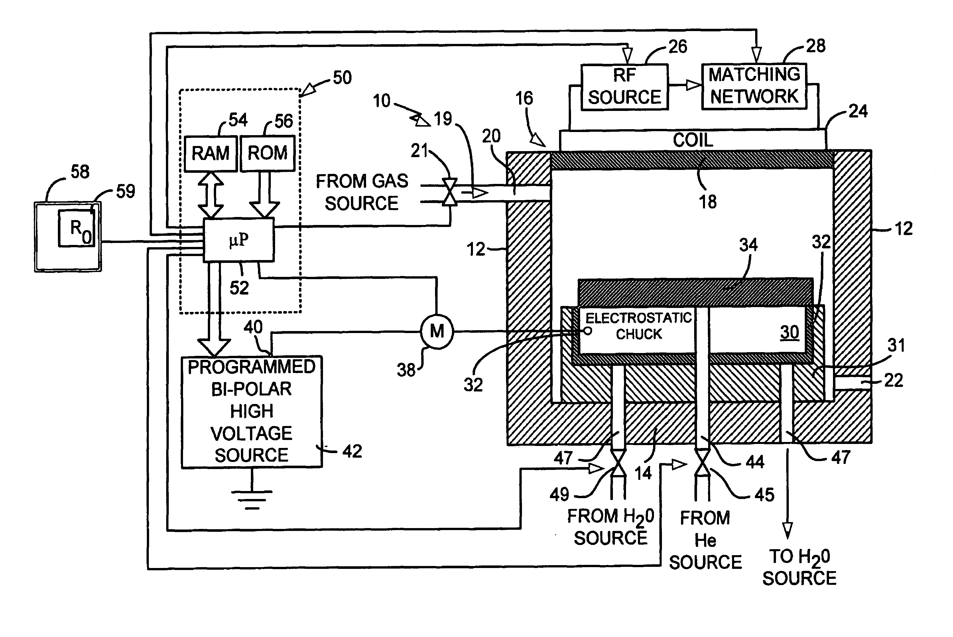
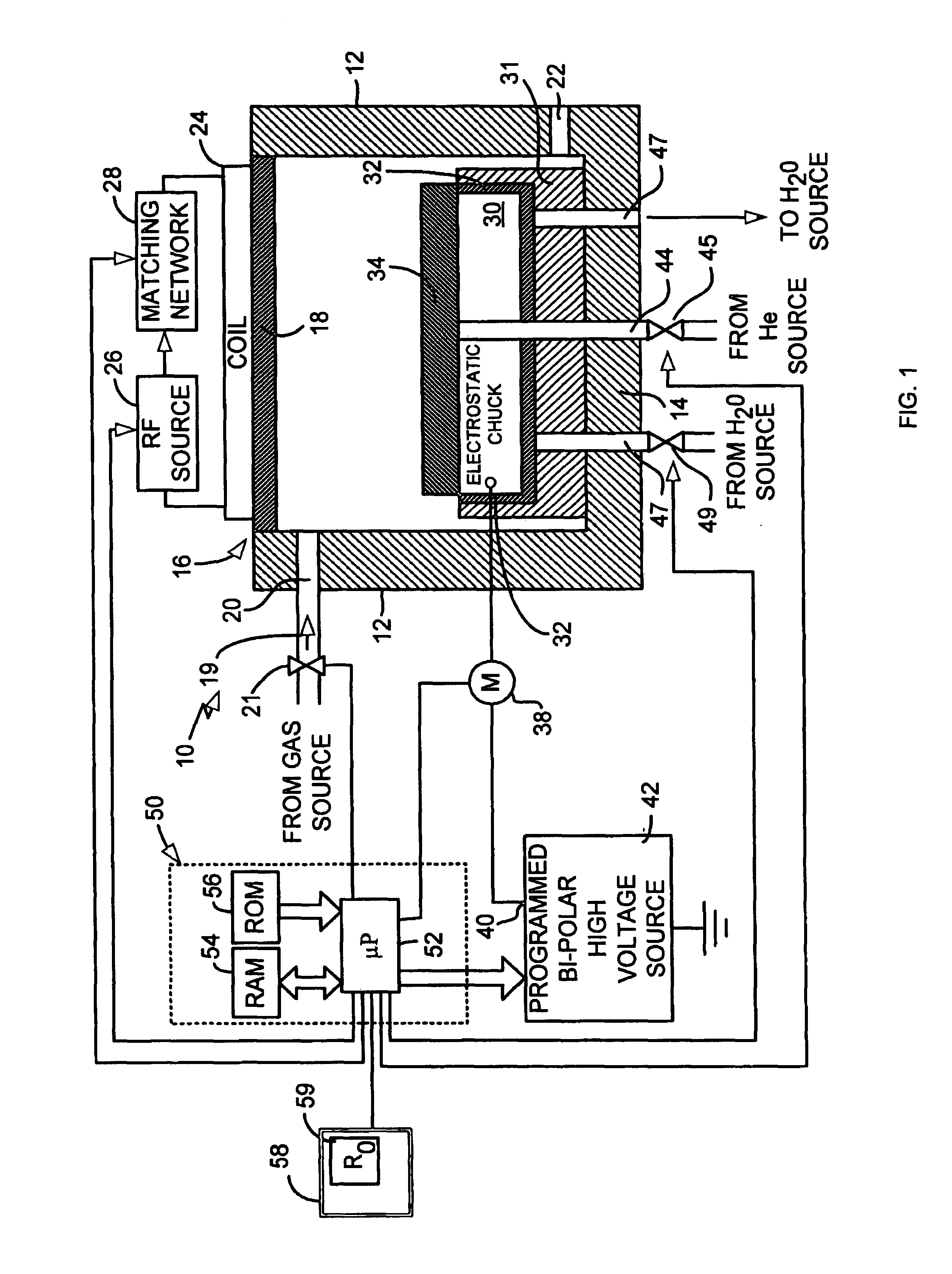
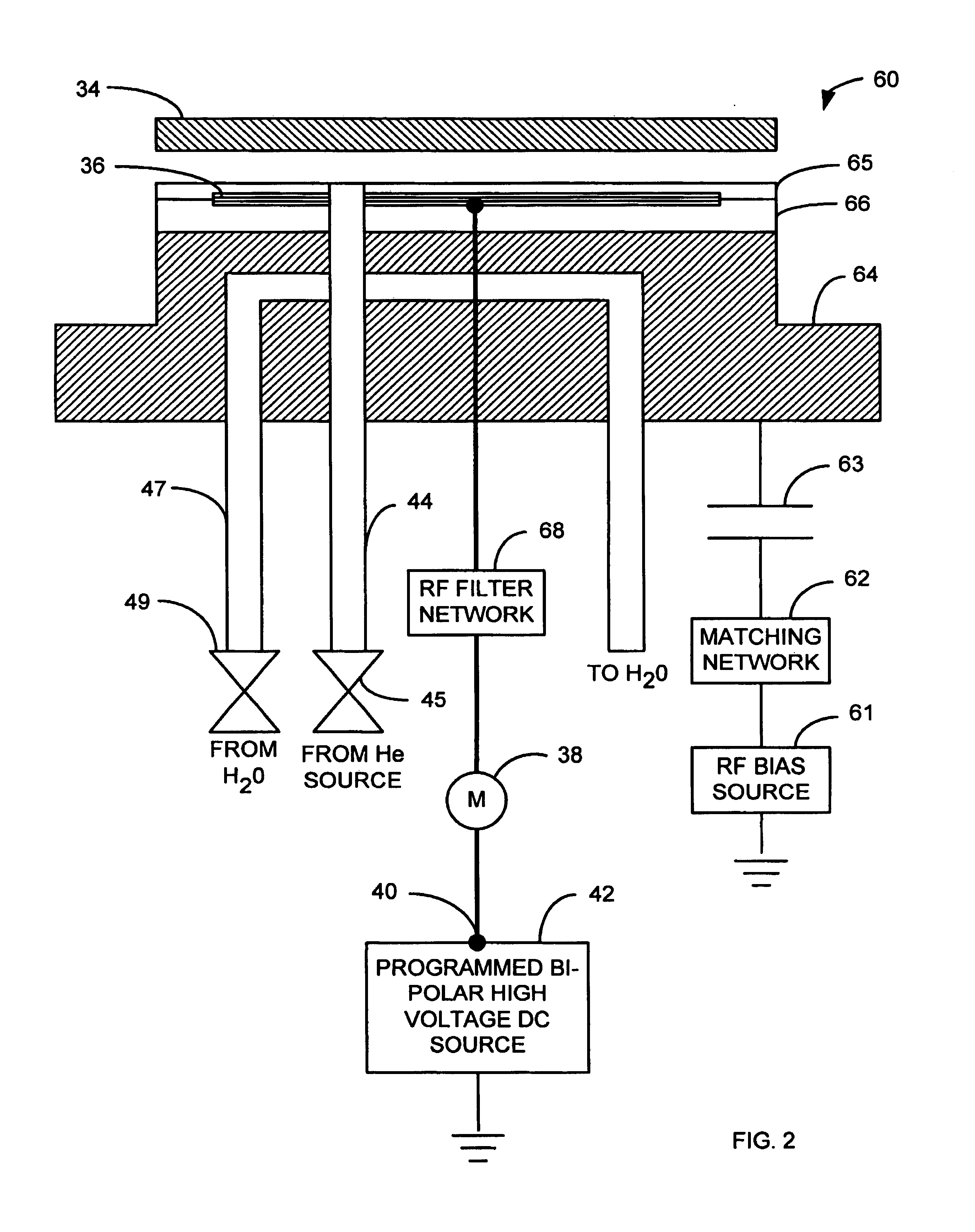
[0040]In the following detailed description, reference is made to the accompanying drawings, which form a part of this application. The drawings show, by way of illustration, specific embodiments in which the invention may be practiced. It is to be understood that other embodiments may be utilized and structural changes may be made without departing from the scope of the present invention.

[0041]This invention provides a system and method for determining the dechucking parameters for an electrostatic chuck (ESC). During the dechucking process a reverse polarity voltage is applied for a time period. It shall be appreciated by those skilled in the art that during the dechucking process that if the reverse polarity magnitude is too small or the time period too short, the workpiece will not be sufficiently dechucked and may stick to the ESC. On the other hand, if the reverse polarity magnitude is too high or the time too long, the wafer may be re-clamped with the opposite polarity, and o...


PUM

PropertyMeasurementUnit
voltageaaaaaaaaaa
DC voltageaaaaaaaaaa
voltageaaaaaaaaaa

Abstract

The present invention comprises a system and method for determining the reverse voltage and time to apply to the dechucking of a workpiece from an electrostatic chuck (ESC). The system for dechucking comprises a processing chamber operatively coupled to a microprocessor and a memory that is configured to determine the dechucking parameters for the workpiece. The method for determining dechucking parameters comprises generating a correlation between ESC resistance and dechucking parameters, performing a single experimental test on a new ESC and generating a fitting parameter, and using the correlation and the fitting parameter to determine the dechucking parameters.

Description

CROSS REFERENCE[0001]The present patent application is a Continuation-In-Part of patent application Ser. No. 09 / 163,368 that was filed on Sep. 30, 1998, now U.S. Pat. No. 6,790,375 and titled “Dechucking Method and Apparatus for Workpieces in Vacuum Processors”. Additionally, the present patent application claims priority of provisional patent application 60 / 322,580 that was filed on Sep. 14, 2001 and is titled “A Dechucking Algorithm for Electrostatic Chucks With Voltage Polarity Reversal.” These applications are hereby incorporated by reference.BACKGROUND OF THE INVENTION[0002]1. Field of Invention[0003]The present invention is related to processing of dielectric or semiconductor materials. More particularly, the invention is related to releasing a dielectric or semiconductor workpiece from an electrostatic chuck.[0004]2. Description of Related Art[0005]During the process of wafer processing or glass processing, an electrostatic chuck (ESC) is used to clamp the semiconductor or di...

Claims


Application Information

Patent Timeline
Patent Type & Authority Patents(United States)
IPC IPC(8): H01L21/67H01L21/683H01L21/00H02N13/00
CPCH01L21/67242H01L21/6831H01L21/6833H02N13/00
Inventor HOWALD, ARTHUR M.
Owner LAM RES CORP
Why Eureka
Try Eureka