Rotary disk storage device and method

a technology of rotary disks and storage devices, applied in the direction of magnetic recording, cleaning recording heads, maintaining head carrier alignment, etc., can solve the problems of small amount of dust introduced, dust-generating sources, loss of flying stability, etc., and achieve the effect of suppressing dust deposition and suppressing dust deposition

Inactive Publication Date: 2005-02-17
HITACHI GLOBAL STORAGE TECH NETHERLANDS BV
View PDF12 Cites 19 Cited by
  • Summary
  • Abstract
  • Description
  • Claims
  • Application Information

AI Technical Summary

Benefits of technology

[0010] Embodiments of the present invention provide a rotary disk storage device, such as a magnetic disk device or optomagnetic disk device, which can suppress deposition of dust particles on the air bearing surface of each head / slider, as well as a method for suppressing deposition of dust particles on the bearing surface of the head / slider in a rotary disk storage device.
[0011] Knowing that dust deposition on the air bearing surface of a head / slider is attributable to the skew angle of the head / slider which changes between positive and negative values while the storage device is operating, that is, to the direction of air entering the leading edge which changes across the perpendicular direction, a feature of the present invention is to configure the device so as not to cause the sign of the skew angle to change. More specifically, the device is configured in such a manner that the skew angle is made substantially always positive or negative in order to prevent the air flow direction from changing across the perpendicular direction.
[0013] If the skew angle of the head / slider is made positive at about 80% or more of all the plurality of tracks, air flows at positive skew angles have substantially larger influence than air flows at negative skew angles. In this case, if dust particles are accumulated on the air bearing surface, they may be quickly or slowly removed by moving air, resulting in the reduced amount of deposition. To effectively prevent the dust deposition, the skew angle of the head / slider is made positive more preferably at about 90% or more and most preferably at 100% of all the plurality of tracks.
[0019] The magnitude of the skew angle should be as small as possible in view of the dependence of the head / slider flying height on the linear speed and the flying stability. The skew angle is smallest at the innermost track and becomes larger toward the outermost track. Thus, by setting the skew angle at the innermost track to zero, it is possible not only to make the skew angle positive at all tracks but also minimize the magnitude of the skew angle at the outermost track.
[0020] According to a third aspect of the present invention, there is provided, in a rotary disk storage device comprising: a rotary disk type recording medium which is rotatably held around a spindle and has a plurality of concentric tracks around the spindle; a head / slider composed of a slider having an air bearing surface and a head; and an actuator suspension assembly on which the head / slider is mounted, a method for preventing dust deposition on the air bearing surface of the head / slider. The method comprises configuring the actuator suspension assembly so as to make the skew angle of the head / slider positive or negative at about 80% or more of the plurality of tracks; rotating the rotary disk type recording medium; facing the air bearing surface of the head / slider toward the rotary disk type recording medium; and swinging the actuator suspension assembly to move the flying head / slider across some of the plurality of tracks on the surface of the rotary disk type recording medium.
[0022] According to embodiments of the present invention, a rotary disk storage device which suppresses dust deposition on the air bearing surface of each head / slider is provided. A method for suppressing dust deposition on the air bearing surface of a head / slider, applicable to rotary disk storage devices, is also provided.

Problems solved by technology

Further, during seek operation, there is a possibility that the flying stability may be lost since the buoyancy dynamically changes.
In the assembling process, however, a small amount of dust is inevitably introduced.
In the assembled HDA, this may cause a dust-generating source.
Further, it is possible that dust penetrates into the HDA through a filter that separates the HDA from the external environment.
However, the prior art methods cannot satisfactorily suppress the deposition of dust particles on the air bearing surface of the head / slider.

Method used


Image

  • Rotary disk storage device and method
  • Rotary disk storage device and method
  • Rotary disk storage device and method

Examples


Embodiment Construction

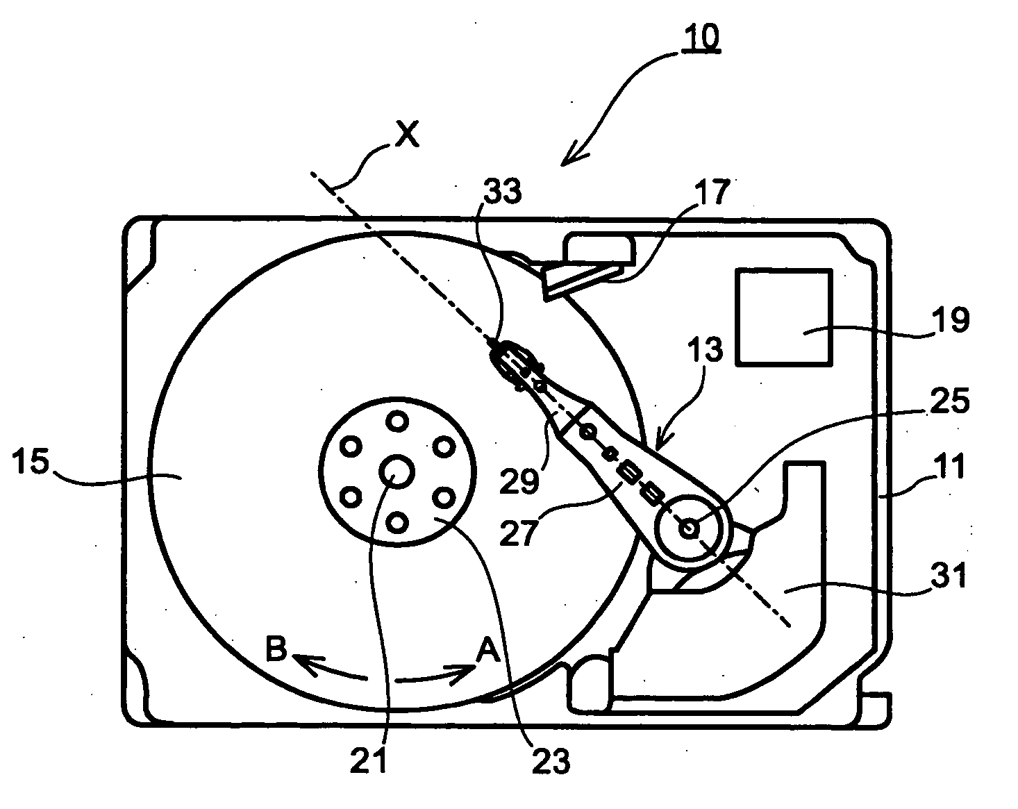
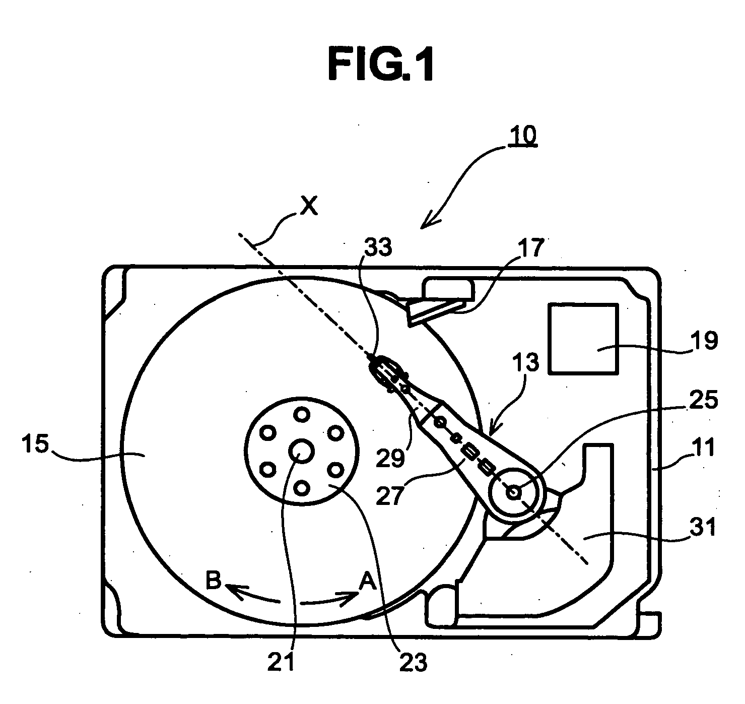
[0037]FIGS. 1 and 2 schematically depict a magnetic disk device 10 and an actuator head suspension assembly (hereinafter denoted as AHSA) 13. Throughout this specification, like components illustrated in each drawing are denoted by like reference numerals. A housing 11, with a housing cover (not shown) attached to its top, defines a sealed space in which an AHSA 13, a magnetic disk stack 15, ramps 17, semiconductor chips and others are accommodated to constitute a head disk assembly (hereinafter denoted as HDA).

[0038] The magnetic disk stack 15 has three disks stacked concentrically with their recording surfaces set parallel to each other. The disks are mounted to a spindle hub (not shown) and fixed by disk pressers 23 so that they are rotated as one by a spindle 21. The magnetic disk stack 15 may have either a single disk or a plurality of disks. Recording surface is formed on the top and bottom sides of each magnetic disk. Each recording surface has a plurality of concentric trac...


PUM

PropertyMeasurementUnit
distance L1aaaaaaaaaa
distance L2aaaaaaaaaa
skew angleaaaaaaaaaa

Abstract

Embodiments of the invention provide a rotary disk storage device in which dust particles are less likely to deposit on the air bearing surface of each head / slider. The actuator head suspension assembly is configured so as to make the skew angle of the head / slider positive at about 80% or more of all the tracks. Specifically, the actuator head suspension assembly is configured in such a manner that the distance L2 between the center of the pivot shaft and the intersection point P of the trailing edge of the head / slider is made longer than a given length or there is an angle β between the reference line Y and the pivot line Z.

Description

BACKGROUND OF THE INVENTION [0001] The present invention relates to magnetic disk devices, optomagnetic disk devices and other rotary disk storage devices provided with a head / slider, and in particular, to a rotary disk storage device which is structured so as to reduce the deposition of dust on the air bearing surface of its head / slider. [0002] In a magnetic disk device, air flow which occurs over the surface of a rotating magnetic disk is guided to the air bearing surface of a head / slider to generate buoyancy which lifts up the head / slider a little from the magnetic disk surface. When data is read / written from / to the magnetic disk, the head / slider is flying in this manner. The spacing kept between the head and the magnetic disk surface must be made as constant as possible since the strength of magnetic coupling between them is affected by the spacing. Further, due to the recent particular tendency for the head / slider to reduce its flying height in step with the rising recording de...

Claims


Application Information

Patent Timeline
Patent Type & Authority Applications(United States)
IPC IPC(8): G11B21/21G11B5/41G11B5/48G11B5/55G11B5/596G11B5/60G11B21/02
CPCG11B5/41G11B5/4833G11B5/4826G11B5/4853G11B5/6082
Inventor TSUDA, SHINGOKAWAMOTO, YASUNORIMATSUMOTO, TSUYOSHINAKAMURA, TAICHI
Owner HITACHI GLOBAL STORAGE TECH NETHERLANDS BV
Why Eureka
Try Eureka