Method and apparatus for minimizing direct coupling for downhole logging devices

a technology of logging device and direct coupling, which is applied in the field of induction well logging, can solve the problems of difficult to distinguish the desired formation signal from the undesired signal, the difficulty of implementing multiple bucking coils on the downhole tool, and the lack of bucking coils shared by the sub-array, so as to minimize the magnitude of the signal, minimize the magnitude of the direct coupling signal, and maximize the space available on the downhole logging tool

Active Publication Date: 2006-04-11
HALLIBURTON ENERGY SERVICES INC
View PDF6 Cites 19 Cited by
  • Summary
  • Abstract
  • Description
  • Claims
  • Application Information

AI Technical Summary

Benefits of technology

[0016]One embodiment includes a transmitting coil, a bucking coil, and a plurality of receiving coils, where signals may be directly coupled from the transmitting coil into the receiving coil and signals may be indirectly coupled from the transmitting coil into the receiving coil. The bucking coil minimizes the magnitude of the signals that are directly coupled from the transmitting coil into multiple receiving coils within the plurality. By varying the current in the bucking coil, the bucking coil minimizes the magnitude of the directly coupled signal in each receiver in the plurality, and each sub-array may utilize a common bucking coil. In this manner, the amount of space available on the downhole logging tool may be maximized.

Problems solved by technology

Also, the magnitude of the direct coupled signal can be several orders of magnitude larger than the signal from the formation, which may make it difficult to distinguish the desired formation signal from the undesired signal that is coupled directly from the transmitter.
Traditional methods and apparatus, however, do not have a bucking coil shared by the sub-arrays.
Since conventional tools normally contain several sub-arrays, multiple bucking coils are often required, yet implementing numerous bucking coils on the downhole tool can be problematic for several reasons.
For some downhole tools, finding a suitable space on the downhole tool for the bucking coils of all sub-arrays can be difficult.
In addition, as more sub-arrays are added to the downhole tool, finding a suitable space on the downhole tool for each bucking coil of each sub-array can be difficult.
In addition, systems that utilize triple component transmit and receive coils (see e.g., U.S. Pat. No. 5,757,191 to Gianzero), may require extra bucking coils associated with each component of the receiving coil and further exacerbate this problem.
This limited number of freedoms is the root cause of all the difficulties described above.

Method used


Image

  • Method and apparatus for minimizing direct coupling for downhole logging devices
  • Method and apparatus for minimizing direct coupling for downhole logging devices
  • Method and apparatus for minimizing direct coupling for downhole logging devices

Examples


Embodiment Construction

[0031]FIG. 2 illustrates a general arrangement of an induction logging tool. A borehole or well 11 is drilled through several earth layers 12, 14, and 16. A logging sonde 20 is suspended within borehole 11 by a logging cable 22. Cable 22 provides mechanical support for the sonde 20 and contains suitable electrical conductors to provide power to the sonde 20 and to transmit control signals from equipment 18 at the surface of the earth to the sonde 20, and to transmit collected data from the sonde 20 to suitable recording media in equipment 18. Although FIG. 2 illustrates a sonde, the embodiments of the invention also may be implemented in LWD applications.

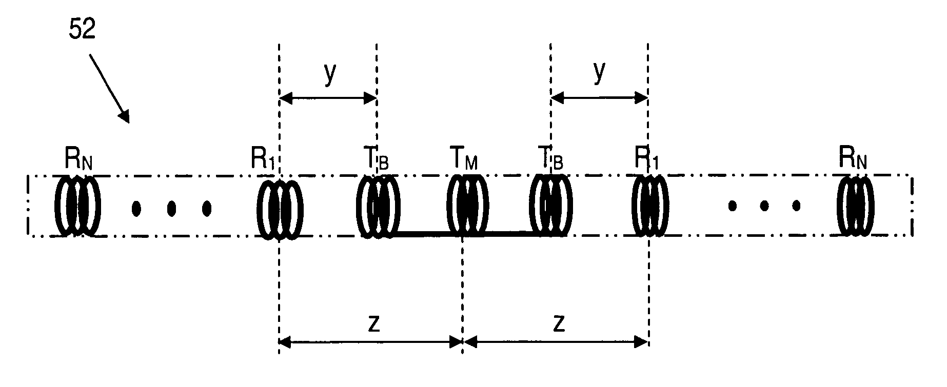
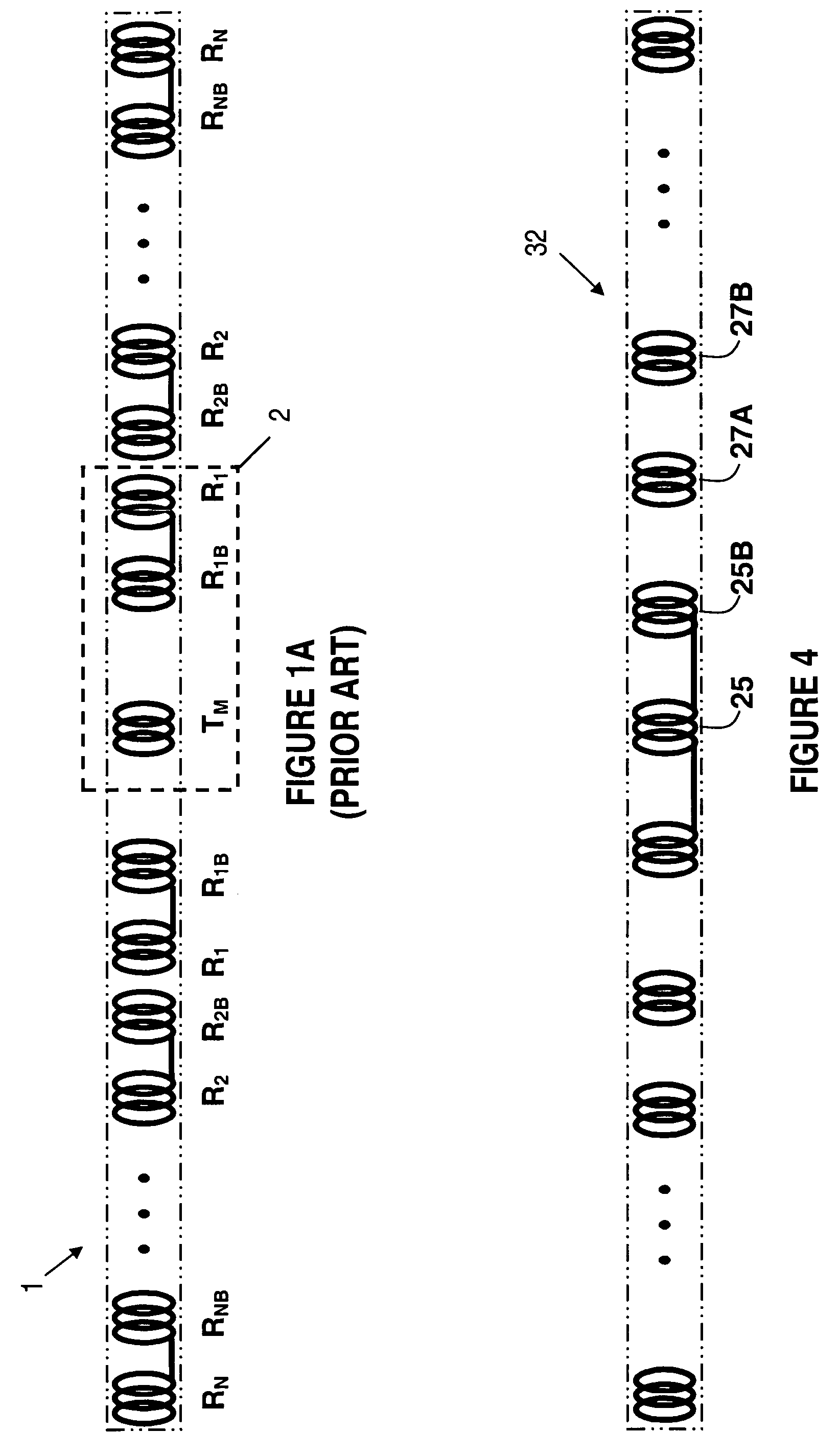
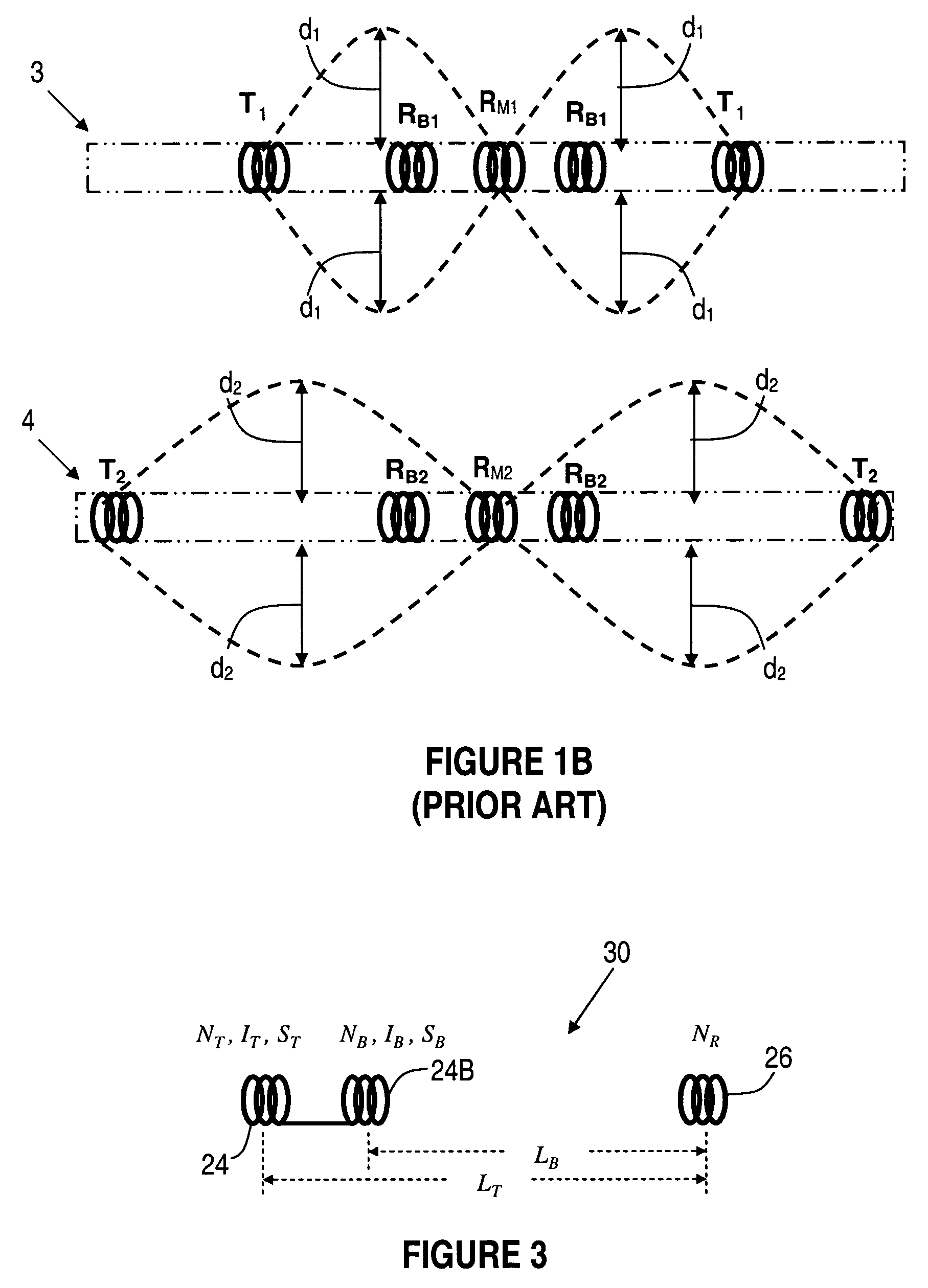
[0032]The sonde 20 is shown with four coil arrangements 24, 24B, 26, and 28. Coil 24 may be used to transmit logging signals and coils 26 and 28 may be used to receive signals. Although only one receiving coil 26 is required for a functional device, in general, induction logging tools have multiple receiver coil arrangements that ar...


PUM


Abstract

A method and apparatus for minimizing direct coupling between transmitters and receivers on a downhole logging tool are disclosed. One embodiment includes a transmitter, a bucking device, and a plurality of receivers, where signals may be directly coupled from the transmitter into the receivers and signals may be indirectly coupled from the transmitter into the receivers through the formation and borehole environment. The bucking device minimizes the magnitude of the signals that are directly coupled from the transmitter into multiple receivers within the plurality. By varying the current in the bucking device, the bucking device minimizes the magnitude of the directly coupled signal of each receiver in the plurality, and each receiver may utilize a common bucking device.

Description

FIELD OF THE INVENTION[0001]This invention relates to induction well logging, and more particularly to a method for minimizing the undesirable coupling effects between downhole transmitters and receivers.BACKGROUND OF THE INVENTION[0002]Modern petroleum drilling and production operations demand a great quantity of information relating to parameters and conditions downhole. Such information typically includes characteristics of the earth formations traversed by the wellbore, in addition to data relating to the size and configuration of the borehole itself. The collection of information relating to conditions downhole, which commonly is referred to as “logging,” can be performed by several methods. Oil well logging has been known in the industry for many years as a technique for providing information to a petrophysicist regarding the particular earth formation being drilled.[0003]In conventional oil well wireline logging, a probe or “sonde” is lowered into the borehole after some or a...

Claims


Application Information

Patent Timeline
Patent Type & Authority Patents(United States)
IPC IPC(8): G01V3/10G01V3/18G01V3/28
CPCG01V3/28
Inventor XIAO, JIAQIGAO, LI
Owner HALLIBURTON ENERGY SERVICES INC
Why Eureka
Try Eureka