
Non-stationary dither code generation and detection

a non-stationary, code generation technology, applied in the direction of radio transmission, electrical equipment, transmission, etc., can solve the problems of conventional transmission methods not meeting both requirements, unable to detect the code structure, and unable to detect the time information in such a signal

Inactive Publication Date: 2005-11-15
HARRIS CORP
View PDF2 Cites 19 Cited by
  • Summary
  • Abstract
  • Description
  • Claims
  • Application Information

AI Technical Summary

Benefits of technology

[0017]A still further object of the present invention is to quickly match a measured code interval with a predetermined code interval.

Problems solved by technology

There are occasions where the timing information in such a signal is to be denied to hostile or unauthorized receivers.
Conventional methods of transmission do not satisfy both requirements of selectively providing timing information only to authorized receivers and providing those receivers with jam-resistant performance for the following reasons.
However, repeating the code implies that some code structure will be observable by an unauthorized receiver.
Conventional repetition of a code will reveal some timing information to unauthorized receivers that could be used to acquire further information from the transmission system, and could compromise its security.
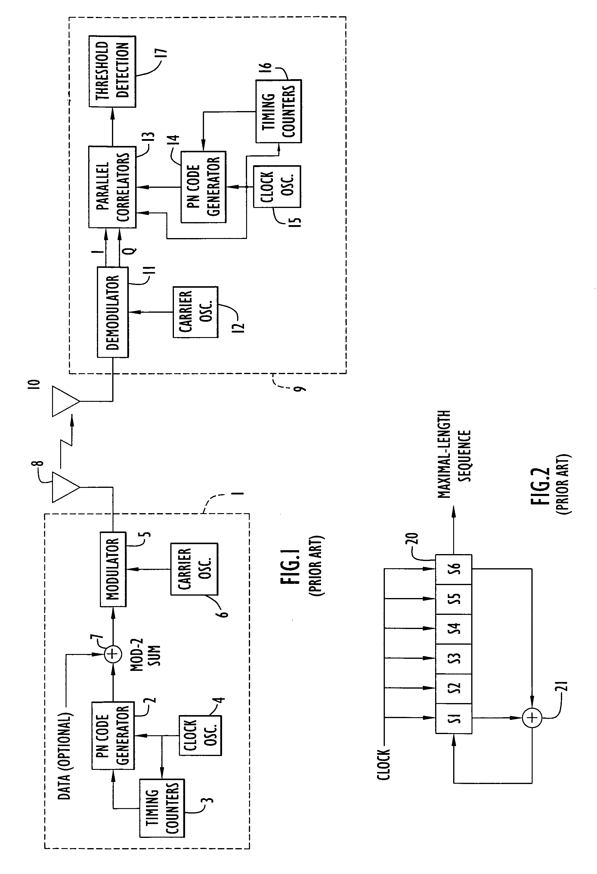
Consequently, conventional spread-spectrum receivers, such as GPS receivers, suffer from the problems described above and are unable to detect a long non-repeating code without the aid of a second timing signal.

Method used


Image

  • Non-stationary dither code generation and detection
  • Non-stationary dither code generation and detection
  • Non-stationary dither code generation and detection

Examples


Embodiment Construction

[0035]Preferred embodiments according to the present invention are described below with reference to the above drawings, in which like reference numerals designate like components.

Overview

[0036]This present invention uses non-stationary dither codes. In contrast, two copending applications entitled “Method And Apparatus For Generating And Transmitting a Stationary Dither Code” and “Method and Apparatus for Detecting a Stationary Dither Code,” which are incorporated herein by reference, describe stationary dither codes. However, those copending application describe stationary codes, and accordingly, stationary codes are described here only briefly.

[0037]Throughout the following description data values and certain parameters are indicated by a compound words formed with no space between the words. For example, “CodeLen” is a data value referring to the length of the a PN code.

Code Structure

[0038]In designing the signal structure for a communications system according to the invention, ...


PUM


Abstract

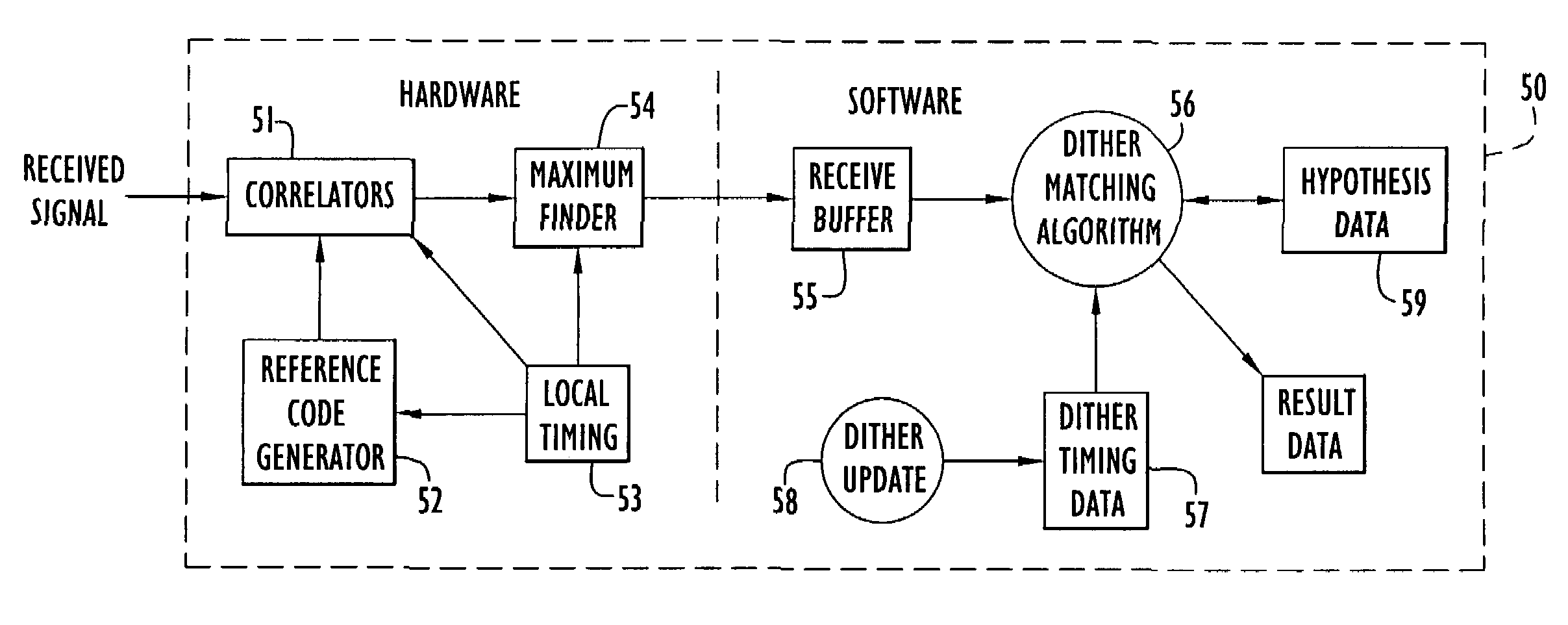
A detector receives a signal and detects from it a long code composed from shorter codes, where the shorter codes are dithered according to a non-repeating dither pattern. The received signal is correlated with a reference code, the correlation sums are ranked, and short codes detected from the ranked sums. Because of a high jamming to signal (J / S) ratio, all the transmitted short codes may not be detected. A dither matching algorithm determines an interval between the detected codes and matches it with a previously stored dither pattern. If there is a strong match, the correlation sums and respective receive times are stored in a hypothesis data structure. If enough subsequent correlation pair have similar matches to exceed a threshold, the match is declared correct and the results are output. The time difference between received and matched pairs can be a measure of a pseudorange between transmitter and receiver.

Description

CROSS REFERENCE TO RELATED APPLICATION[0001]This application claims priority from U.S. Provisional Patent Application Ser. Nos. 60 / 164,951, entitled “Non-stationary Dither Code Detection,” and 60 / 164,952, entitled “Optimal Stationary Dither Code,” both filed Nov. 12, 1999. The disclosures of those provisional patent applications are incorporated herein by reference in their entirety.BACKGROUND OF THE INVENTION[0002]1. Field of the Invention[0003]The present invention relates to data communication systems and, more particularly, to data communication systems using codes with coding boundaries that vary according to a dithering pattern.[0004]2. Description of the Related Art[0005]Pseudo-noise (PN, or pseudorandom) codes are ideal for ranging, that is, measuring the time-of-arrival of a signal, in noisy conditions, including jamming noise, because of the high coding gain and fine timing resolution that can be achieved using PN codes. There are occasions where the timing information in ...

Claims


Application Information

Patent Timeline
IPC IPC(8): H04B1/69H04B1/707
CPCH04B1/70735
Inventor CLARK, JAMES M.
Owner HARRIS CORP
Learn More