Double fire attachment and method for semi-automatic firearms

a double-fire attachment and semi-automatic technology, applied in the field of double-fire attachment and method of semi-automatic firearms, can solve the problems of multiple components and extra tools, screwdrivers, wrenches, etc., and achieve the effects of simple, reliable attachment, and increased firing ra

Inactive Publication Date: 2005-11-22
DECKARD CHRISTOPHER DAVID
View PDF14 Cites 44 Cited by
  • Summary
  • Abstract
  • Description
  • Claims
  • Application Information

AI Technical Summary

Benefits of technology

[0014]The novel invention allows for a double-fire mode where a firearm fires upon a single pull of a trigger, and fires again upon a single release of the trigger.
[0015]The novel trigger attachment device and method allows for various rates of fire other than the available semi-automatic and automatic rates of current firearms. The invention provides a simple, reliable attachment which can be quickly and easily attached to the semi-automatic firearm for increasing the firing rate up to a double-fire mode without causing automatic firing of the semi-automatic firearm.
[0016]The attachment causes the firearm to fire upon release of the trigger by separating the foot of the safety sear from the top of the trigger plate rotating the safety sear rearward on its pivot point which causes an increased gap between the trigger sear, at its hammer engaging notch, and the safety sear, at its hammer engaging notch allowing the hammer to pass through this increased gap upon release of the trigger.
[0017]The attachment can be constructed from a single component shaped to fit and mount onto the trigger with two tab-like features on either side that bend around to the

Problems solved by technology

Automatic firearms are also known to be more expensive and harder to acquire than semi-automatic firearms.
However, these devices require multiple components and extra tools such as screwdrivers, wrenches and pliers, and the like, that require extra fasteners such as screws, and the like.
The prior art converter devices must then be carefully assembled and can take excessive amounts of time for proper assembly in order to work.
Some of these converter devices further require extensive modifications such as opening up and/or drilli

Method used


Image

  • Double fire attachment and method for semi-automatic firearms
  • Double fire attachment and method for semi-automatic firearms
  • Double fire attachment and method for semi-automatic firearms

Examples


Embodiment Construction

[0031]Before explaining the disclosed embodiments of the present invention in detail it is to be understood that the invention is not limited in its application to the details of the particular arrangement shown since the invention is capable of other embodiments. Also, the terminology used herein is for the purpose of description and not of limitation.

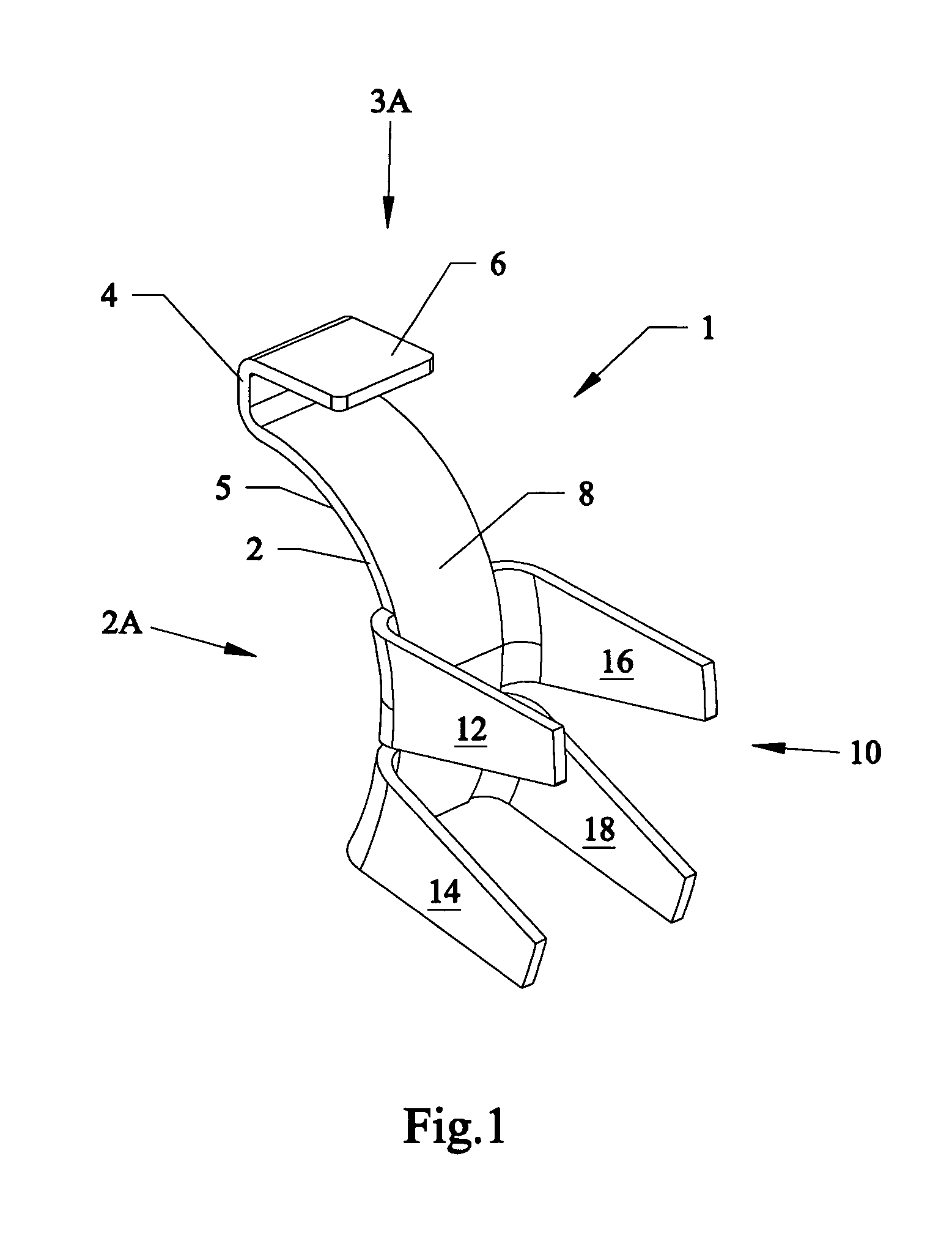
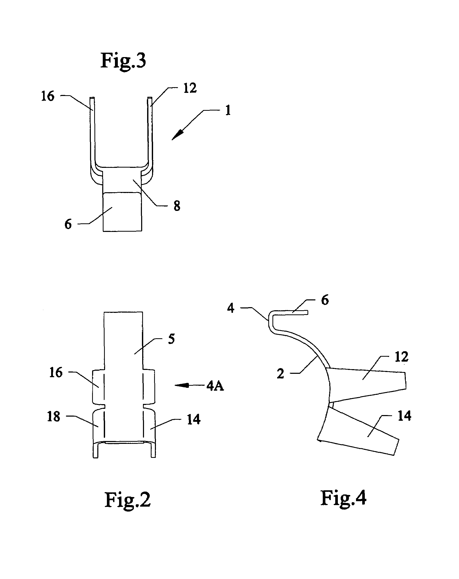
[0032]FIG. 1 shows a perspective view of a first preferred embodiment of a double fire spacer 1. FIG. 2 is a front view of the double fire spacer 1 of FIG. 1 along arrow 2A. FIG. 3 is a top view of the double fire spacer 1 of FIG. 1 along arrow 3A. FIG. 4 is a side view of the double fire spacer 1 of FIG. 4 along arrow 4A.

[0033]Referring to FIGS. 1–4, the double fire spacer 1 can be clip having a curved backing member 2 with bent portion 4 having an upper flange member 6. Extending from lower concave curved portion 8 of the backing member 2 can be clipping end 10 having four protruding bendable tab members 12, 14, 16, 18, with two tab...


PUM


Abstract

Devices and methods of converting semi-automatic firearms to a double-fire mode where a firearm fires a shot upon a single pull of a trigger, and fires a second shot upon a release of the trigger. A clip attachment can be constructed from a single component shaped to fit and mount onto the trigger and extend to protrude between and separate the foot of the safety-sear from the top of the trigger plate affecting the distance between the hammer engaging notch of the safety-sear and the hammer engaging notch of the trigger-sear which allows the firearm to discharge upon release of the trigger. Another version has a spacer pre-built onto a bottom portion of the pivotal safety sear.

Description

FIELD OF INVENTION[0001]This invention relates to firearms, and in particular to retrofit devices and methods and pre-built devices and methods for increasing the firing rate of semi-automatic firearms, such as but not limited to AK type rifles, to a double-fire mode where two shots are fired with a single pull and release of a trigger.BACKGROUND AND PRIOR ART[0002]Semi-automatic firearms have a limited firing rate which does not approach the firing rate of automatic firearms. Automatic firearms are also known to be more expensive and harder to acquire than semi-automatic firearms. As a result, many devices have been proposed over the years for increasing the firing rate of semi-automatic firearms. See for example, U.S. Pat. No.: 3,184,875 to Klebe; U.S. Pat. No. 4,344,351 to McQueen; U.S. Pat. No. 4,787,288 to Miller; and U.S. Pat. Nos. 4,803,910 and 5,074,190 both to Troncoso.[0003]However, these devices require multiple components and extra tools such as screwdrivers, wrenches an...

Claims


Application Information

Patent Timeline
IPC IPC(8): F41A19/00F41A19/24F41A19/30
CPCF41A19/24F41A19/30
Inventor DECKARD, CHRISTOPHER DAVID
Owner DECKARD CHRISTOPHER DAVID
Why Eureka
Try Eureka