Drive mechanism for a conveyor with stretching compensation means

a technology of compensation means and drive mechanism, which is applied in the direction of conveyors, transportation and packaging, etc., can solve the problems of conveyor member stretching, noise, and partial lifting of conveying members, and achieve the effect of satisfying force guidance and reducing friction on the slide bars

Inactive Publication Date: 2005-11-22
BOSCH REXROTH AG
View PDF12 Cites 5 Cited by
  • Summary
  • Abstract
  • Description
  • Claims
  • Application Information

AI Technical Summary

Benefits of technology

[0010]Especially a uniform, noise-free and trouble-free operation of the conveying member is obtained with the above-described drive device or drive mechanism according to the invention. This takes place independently of the respective operating conditions, especially the load, the tension, the operating temperature and other parameters. Sat

Problems solved by technology

In continuous conveyors that are currently known high tension or pulling force and temperatures influences lead to stretching of the conveyor member.
As a result forces,

Method used


Image

  • Drive mechanism for a conveyor with stretching compensation means
  • Drive mechanism for a conveyor with stretching compensation means

Examples


Embodiment Construction

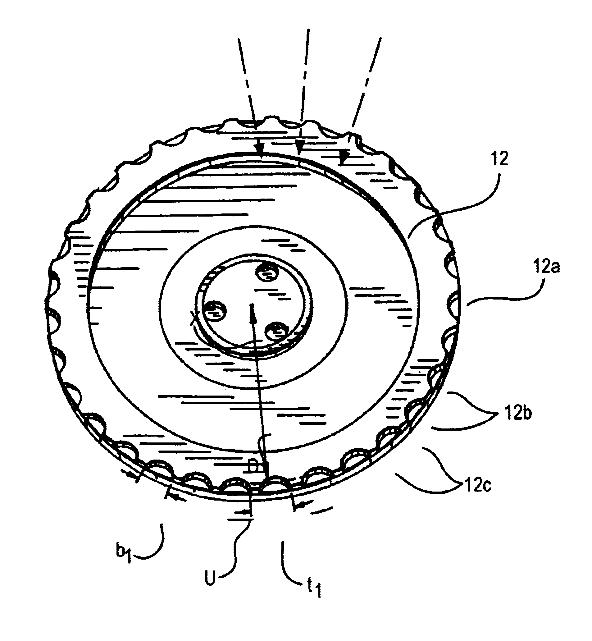
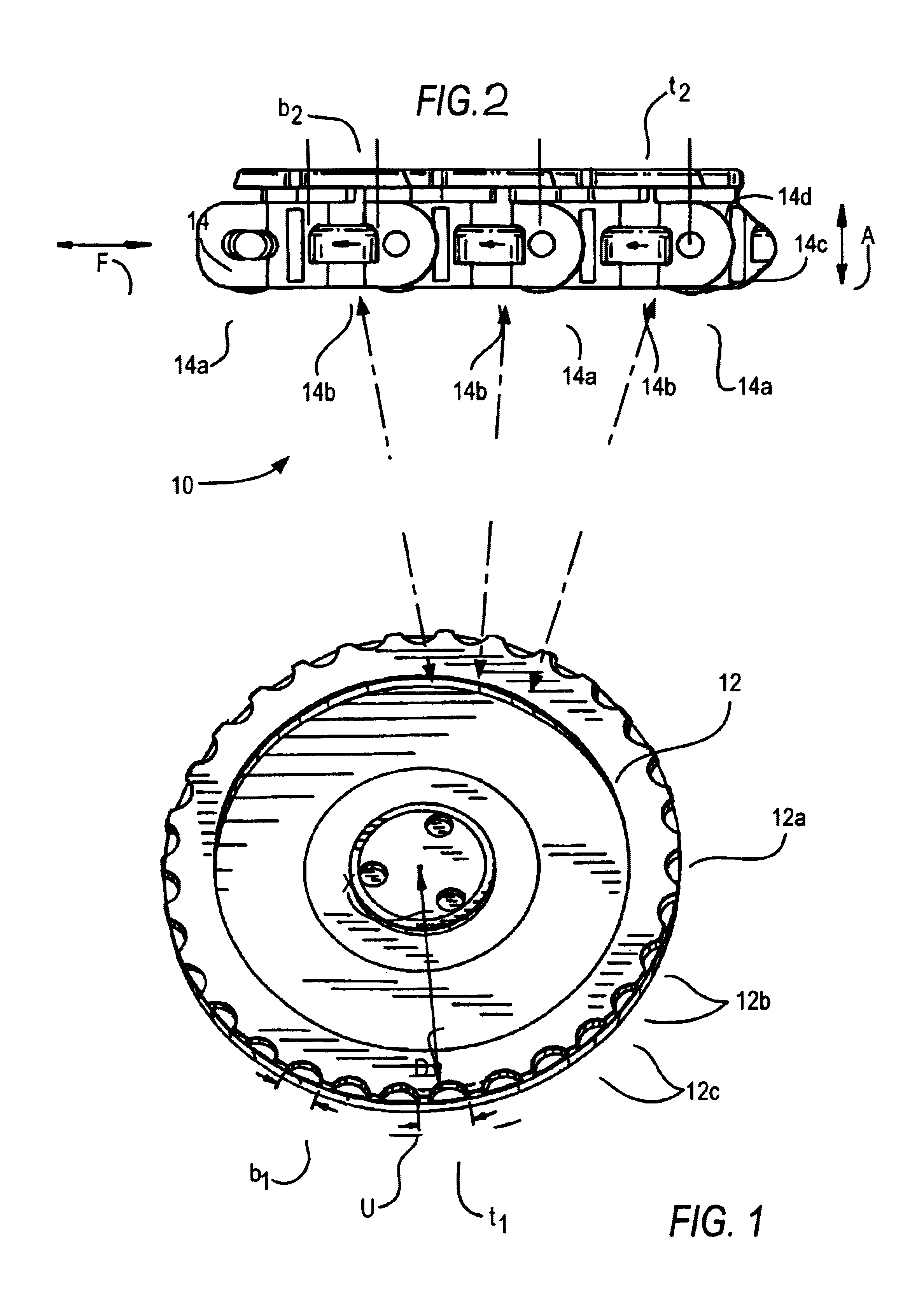
[0014]In FIGS. 1 and 2 the reference number 10 designates the drive mechanism according to the invention. It comprises a drive wheel 12 and a conveyor chain 14.

[0015]The drive wheel 12 is serrated or toothed on its outer periphery 12a, which means that it includes a plurality of engaging elements, specifically teeth, 12b, which engage with the conveyor chain 14. The engaging elements (teeth) 12b are separated from each other by indentations 12c. The engaging element spacing on the drive wheel 12, which means the interval, with which the engaging elements 12b are spaced from each other, is indicated in FIG. 1 with t1. The width of the indentation 12c is designed with b1.

[0016]The conveyor chain 14 is assembled from a plurality of chain members 14a. These chain members 14a include counter elements 14b on their side surfaces, which engage with the drive wheel 12 of the conveyor chain 14. The counter element spacing of the conveyor chain 14, which means the spacing between successive pi...


PUM


Abstract

The drive mechanism (10) has a drive member (12) and a flexible conveying member (14). The engaging elements (12b) of the drive member (12) have an engaging element spacing (t1), while the associated counter elements (14b) of the conveyor member 14 have a counter element spacing (t2). According to the invention the engaging element spacing (t1) of the engaging elements (12b) is larger than the counter element spacing (t2) of the counter elements (14b) of the conveying member in order to compensate for conveyor member stretching in operation. In a preferred embodiment the conveying member is a flexible conveyor chain and the drive member (12) is a toothed drive wheel. In another preferred embodiment the ratio of the engaging element spacing (t1) of the drive member (12) to the counter element spacing (t2) of the conveying member (14) is between about 1.01 and about 1.10.

Description

BACKGROUND OF THE INVENTION[0001]The present invention relates to a drive device for a conveyor, comprising a drive member with a plurality of engaging elements arranged on the drive member with an engaging element spacing and a flexible conveying member with a plurality of counter elements arranged on the conveyor chain with a counter element-spacing, wherein the engaging elements and the counter elements are arranged so that they can engage with each other so that the conveying member can be driven with the drive member.[0002]Drive devices of this kind, for example, are used in continuous conveyors for manufacturing and assembly apparatus, such as from the catalog “Chain Conveyor System—Varioflow” of Robert Bosch GmbH. This continuous conveyor includes a flexible conveying member, for example a special chain or a special toothed belt, for transporting the conveyed goods. Usually a drive wheel is used as the drive member, for example, with engaging elements in the form of teeth. By...

Claims


Application Information

Patent Timeline
IPC IPC(8): B65G23/00B65G23/06
CPCB65G23/06
Inventor KOBAN, JOHANNESNEUBER, MICHAELRAHNFELD, FRANK
Owner BOSCH REXROTH AG
Why Eureka
Try Eureka