In-flight refueling system, alignment system, and method for automatic alignment and engagement of an in-flight refueling boom

a technology for refueling booms and in-flight refueling, which is applied in the field of in-flight refueling, can solve the problems of difficult positioning and maintenance of boom positions relative to the refueling receptacle, and serious damage to the second aircraft,

Active Publication Date: 2005-11-22
THE BOEING CO
View PDF19 Cites 97 Cited by
  • Summary
  • Abstract
  • Description
  • Claims
  • Application Information

AI Technical Summary

Benefits of technology

[0010]Thus, the various embodiments of the in-flight refueling system, alignment system, and method of the present invention provide many advantages that may include, but are not limited to: the ability to provide a substantially automated alignment between an in-flight refueling boom carried by a first aircraft and a refueling receptacle carried by a second aircraft, the ability to detect and automatically maintain alignment between the in-flight refueling boom and the refueling receptacle, and the ability to automatically extend an extendable nozzle from the in-flight refueling boom to the refueling receptacle so as to initiate an in-flight refueling operation. These features may allow an operator of the in-flight refueling system to focus attention on safety and fue

Problems solved by technology

The requirement of precise relative spatial positioning of two rapidly moving aircraft makes in-flight refueling a challenging operation.
As both the first and second aircraft may be traveling at hundreds of miles per hour through areas of turbulence created both by atmospheric conditions and the aerodynamic forces of the control surfaces of the aircraft, the positioning and maintenance of boom position relative to the refueling receptacle may be extremely difficult.
Furthermore, if the refueling nozzle is extended (typically at a rate of 1 to 4 feet per second) while the boom and refueling receptacle are out of alignment, the nozzle may impact the second aircraft at a position other than the in-flight refueling receptacle, th

Method used


Image

  • In-flight refueling system, alignment system, and method for automatic alignment and engagement of an in-flight refueling boom
  • In-flight refueling system, alignment system, and method for automatic alignment and engagement of an in-flight refueling boom
  • In-flight refueling system, alignment system, and method for automatic alignment and engagement of an in-flight refueling boom

Examples


Embodiment Construction

[0018]The present inventions now will be described more fully hereinafter with reference to the accompanying drawings, in which some, but not all embodiments of the invention are shown. Indeed, these inventions may be embodied in many different forms and should not be construed as limited to the embodiments set forth herein; rather, these embodiments are provided so that this disclosure will satisfy applicable legal requirements. Like numbers refer to like elements throughout.

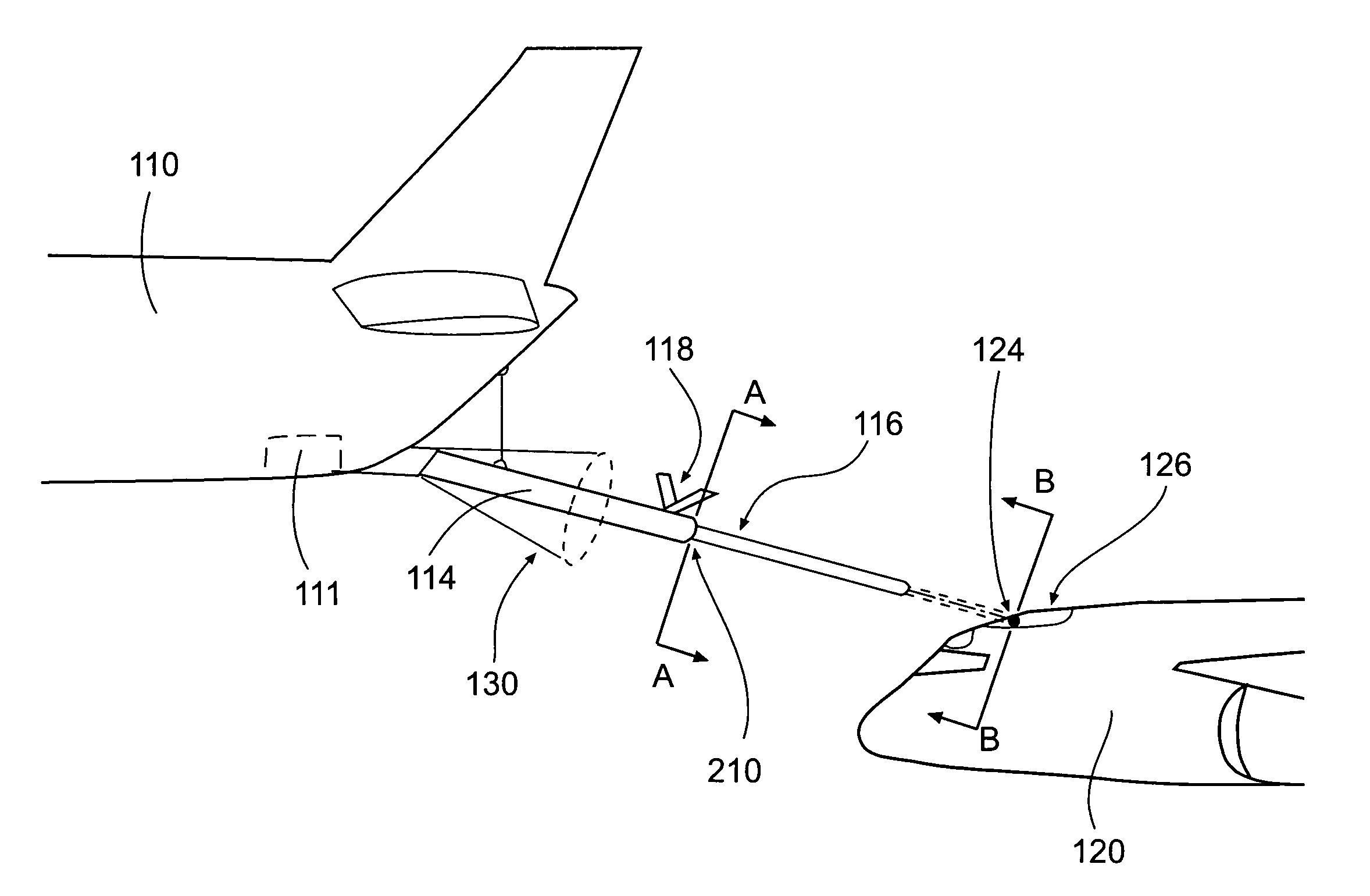
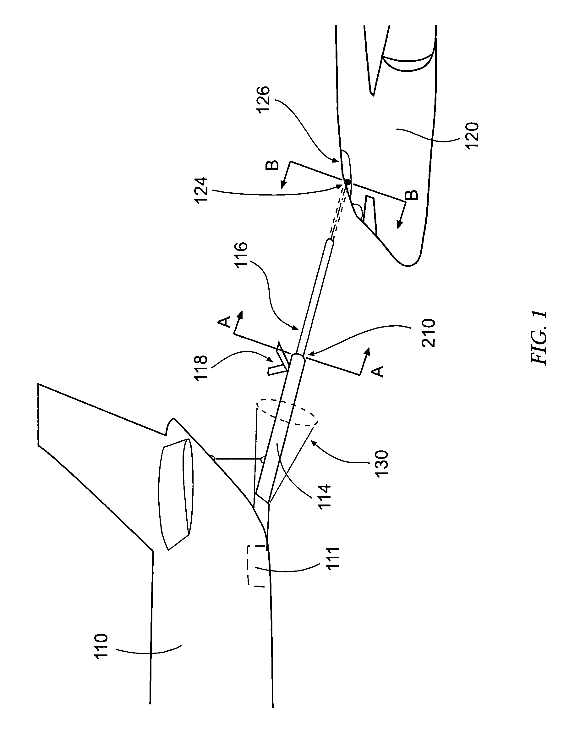
[0019]FIG. 1 shows an in-flight refueling operation between a first aircraft 110 and a second aircraft 120, wherein the first aircraft may be adapted to carry an in-flight refueling boom 114 as part of an in-flight refueling system, and the in-flight refueling boom 114 may be configured to be guided into alignment with a refueling receptacle 126 carried by the second aircraft 120. For instance, the refueling boom 114 may be guided into alignment with the refueling receptacle 126 by adjusting the airfoils 118 op...


PUM


Abstract

An in-flight refueling system, alignment system, and method are provided for substantially automating the positioning and engagement of an in-flight refueling system carried by a first aircraft with respect to a refueling receptacle carried by a second aircraft so as to facilitate an in-flight refueling operation between the first and the second aircraft. More specifically, the present invention provides for the alignment of the in-flight refueling boom with the refueling receptacle such that an extendable nozzle may extend from the in-flight refueling boom and engage the refueling receptacle to initiate an in-flight refueling operation.

Description

FIELD OF THE INVENTION[0001]The present invention relates generally to in-flight refueling of a manned or unmanned aircraft using a boom in-flight refueling system, and specifically, providing optical and / or electronic alignment devices carried by first and / or second aircraft so as to provide guidance to a refueling boom carried by the first aircraft such that the refueling boom may automatically engage a refueling receptacle carried by the second aircraft as part of an in-flight refueling operation.BACKGROUND OF THE INVENTION[0002]In-flight refueling (or air-to-air refueling) is an important method for extending the range of both manned and unmanned aircraft traveling long distances over areas having no feasible landing or refueling points. Although in-flight refueling is a relatively common operation, especially for military aircraft, precise positioning of a second aircraft (the receiver aircraft, for example) with respect to a first aircraft (the tanker aircraft, for example) is...

Claims


Application Information

Patent Timeline
IPC IPC(8): B64C1/00B64D39/00
CPCB64D39/00
Inventor SCHROEDER, STEVEN B.
Owner THE BOEING CO
Why Eureka
Try Eureka