Wrap-around notebook

a notebook and wrap-around technology, applied in the field of notebooks or binders, can solve the problems of difficult to secure the hinge plate to the spine or to the assembly cover, and achieve the effects of avoiding sharp corners, improving the aesthetic appearance of the shield/frame, and reducing costs

Inactive Publication Date: 2005-11-22
CCL LABEL INC
View PDF27 Cites 7 Cited by
  • Summary
  • Abstract
  • Description
  • Claims
  • Application Information

AI Technical Summary

Benefits of technology

[0011]3. The frame / shield assemblies are shortened with respect to the height of the notebook to reduce costs, and the ends are curved to avoid sharp corners, and to improve the aesthetic appearance of the shield / frame assembly.
[0012]4. The single hinge plate extending the majority of the length of the frame / shield assembly may be replaced by two small hinge plates located to include the the rivet openings for securing the shield / frame assembly to the binder, as a cost reduction step.
[0013]5. The exposed frame members are plated with a silver colored plating, such as nickel, zinc or chromium, to preclude rusting and to provide a more aesthetically pleasing appearance.
[0017]Advantages of the present design include an improved aesthetic configuration, a reduction in costs resulting from eliminating the need for a second shield, reduction in the length of the ring assembly, and optionally using two small hinge plates instead of one long hinge plate.

Problems solved by technology

Thus, for example, it can be difficult to secure the hinge plate to the spine or to a cover of the assembly with the hinge plate being in a different plane from the upper surface of the shield.
In addition, the flat unfinished frames with protruding ring rivets are rough and unsightly, so that in some cases a second shield was considered desirable to improve the appearance of the notebook.

Method used


Image

  • Wrap-around notebook
  • Wrap-around notebook
  • Wrap-around notebook

Examples


Embodiment Construction

[0028]While the specification describes particular embodiments of the present invention, those of ordinary skill can devise variations of the present invention without departing from the inventive concept.

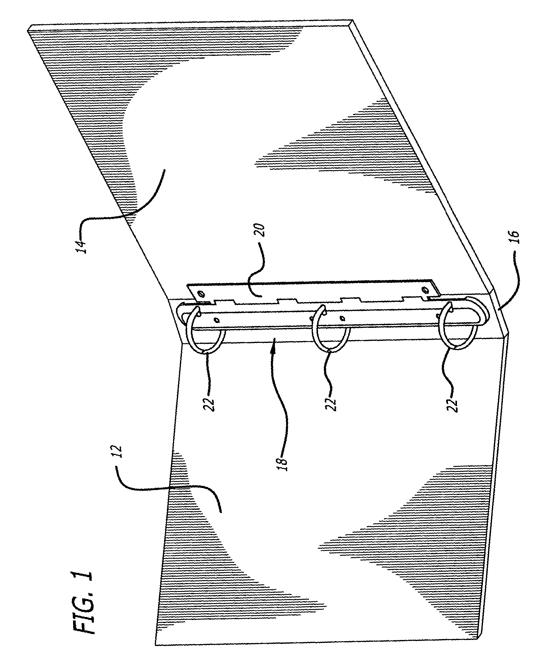
[0029]Referring more particularly to the drawings, FIG. 1 shows a notebook having two covers 12, 14 and a spine panel 16 hinged to the two covers. A ring assembly 18 is shown pivotally mounted to the notebook by the hinge panel 20. The rings 22, which may be opened or closed, are mounted on frames included in the ring assembly as discussed in greater detail hereinbelow.

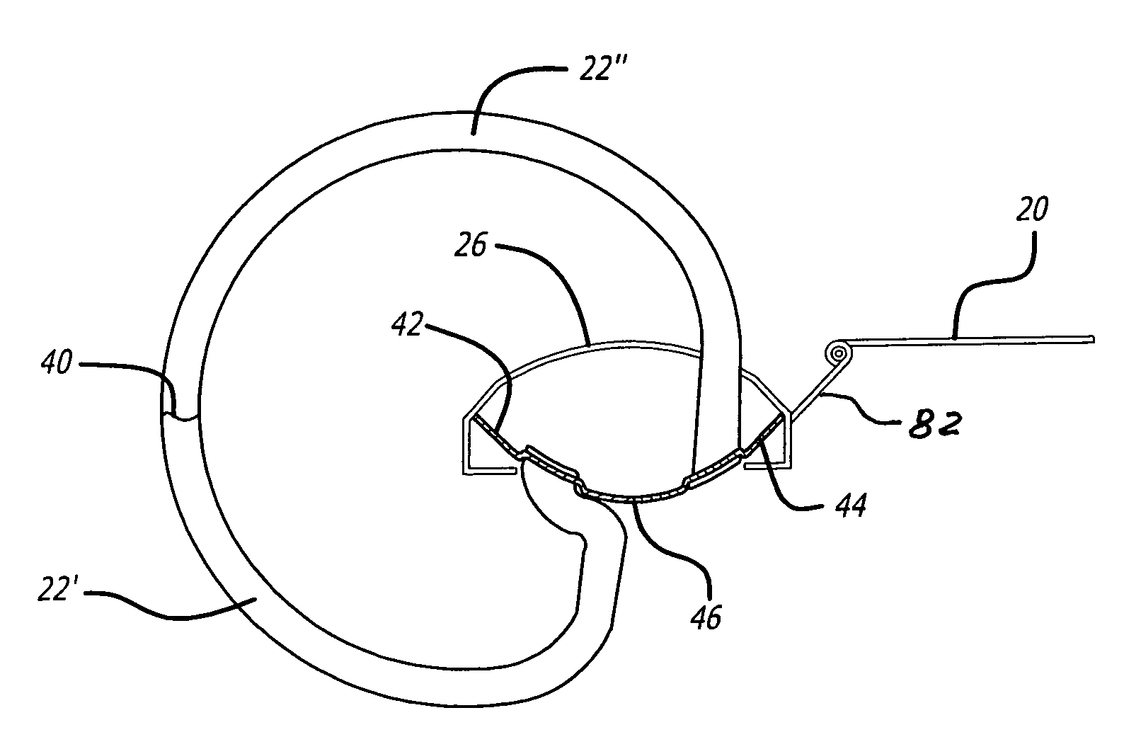
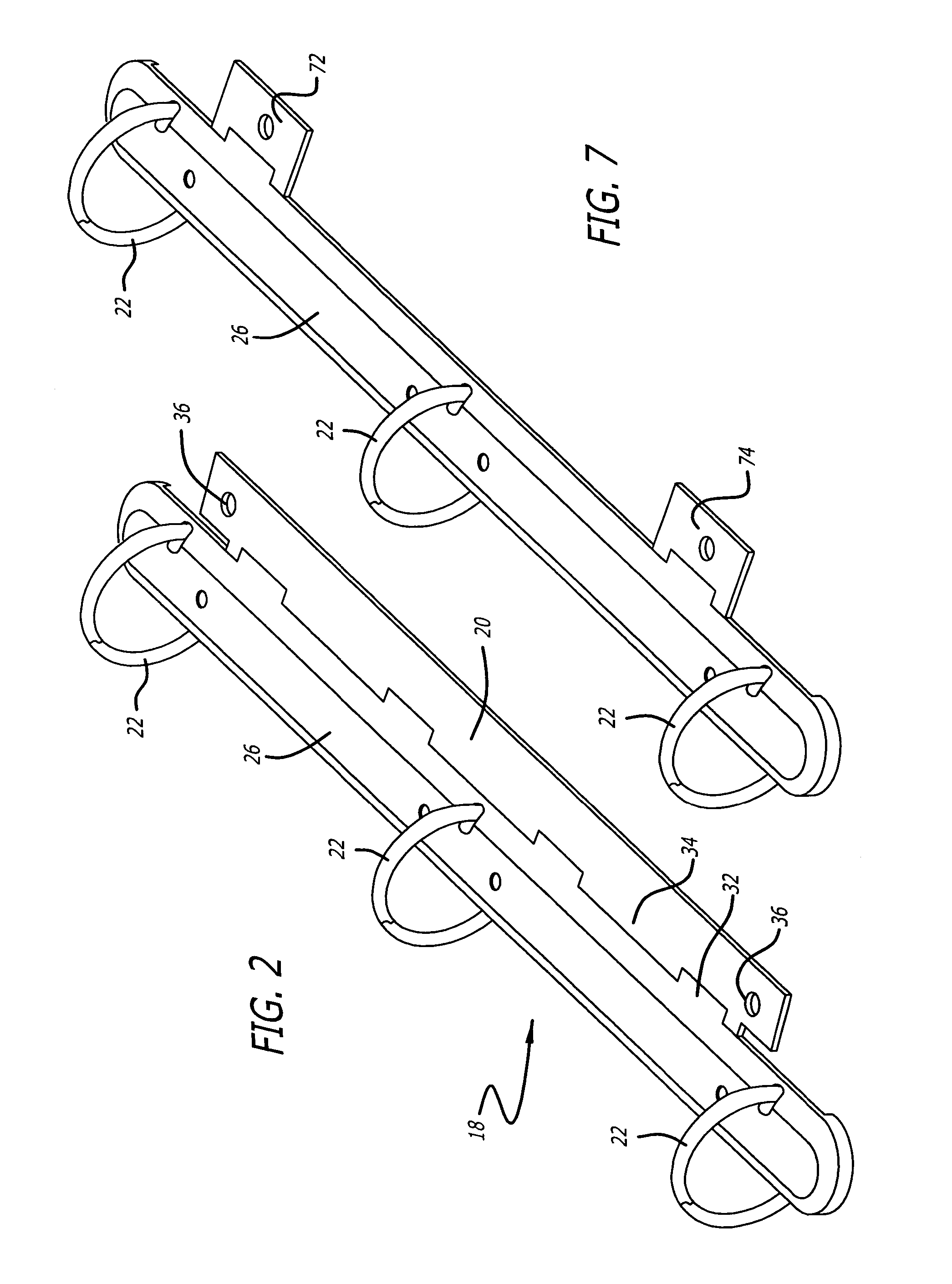
[0030]FIG. 2 is a perspective view of the ring assembly 18 and the hinge plate 20. The pivot between the ring assembly 18 and the hinge plate 20 is implemented by alternate lateral extensions from the shield 26 and the hinge plate 20, which extensions are curled to have a central aligned opening through which a wire extends. The first curl from the shield 26 may be noted at reference numeral 32, and the first curl fr...


PUM


Abstract

A wrap-around notebook or binder includes a ring assembly with a shield and a pair of frames forming a bistable construction, and a hinge plate pivotally coupled to the shield with the outer surface of the hinge plate aligned with the outer extent of the shield / frame assembly when the hinge plate is parallel to the plane of the shield. The exposed frame member may be convex, recessed to receive rivet heads, and may be plated. The hinge plate(s) may have curls which interfit with alternate curls from the shield to provide a hinge. The ring assembly may be mounted in the notebook or binder so that the shield side of the ring assembly faces the front cover of the binder. The pivot line between the shield and the hinge plate may be spaced from the shield by a clearance distance. The notebook or binder lies flat on an underlying surface with either the front cover of the rear cover folded under the assembly.

Description

FIELD OF THE INVENTION[0001]This invention relates to notebooks or binders of the “wrap-around” type.BACKGROUND OF THE INVENTION[0002]Conventional ring binder notebooks have a ring assembly secured to the binding or to one of the two covers of the notebook near the binding. The ring mechanism normally has three rings mounted so that there are two stable positions for the rings, with the rings being either open to facilitate insertion or removal of sheets of paper, or closed to hold the sheets in place. To obtain these two stable positions for the rings, an assembly is provided using two long stiff rectangular plates, known in the binder field as “frames”.[0003]These two frames are pivotally coupled together along an inner longitudinal edge of each frame. A springy overlying metal strip known in the binder field as a “shield”, engages the outer edges of the two strips and biases them inward to provide two bistable states for the frames, with the frames making an oblique angle relativ...

Claims


Application Information

Patent Timeline
Patent Type & Authority Patents(United States)
IPC IPC(8): B42F13/26B42F13/00B42F13/22
CPCB42F13/22Y10T24/20
Inventor SATO, JAY K.WHALEY, PAUL
Owner CCL LABEL INC
Why Eureka
Try Eureka