Compressor airfoils with movable tips

a compressor blade and airfoil technology, applied in the direction of rotors, marine propulsion, vessel construction, etc., can solve the problems of fluid leakage across the tips of the compressor blades, the operation efficiency of the turbine engine is less than the theoretical maximum, and the leakage occurs across the space between. to achieve the effect of preventing overextension and increasing the power and efficiency of the engin

Active Publication Date: 2005-11-22
SIEMENS ENERGY INC
View PDF13 Cites 21 Cited by
  • Summary
  • Abstract
  • Description
  • Claims
  • Application Information

AI Technical Summary

Benefits of technology

[0010]The tip insert is radially outwardly movable against the bias of the spring from the predetermined recessed position up to a predetermined extended position. An abutment surface can be provided within the pocket for engaging at least one of the tip insert and the spring so as to limit the extension of the tip insert to the predetermined extended position. Limiting the movement of the tip insert can prevent overextension so that the tip insert does not impinge on the surrounding stationary structure and that the operational limits of the spring operatively associated with the tip insert are not exceeded. When moving from the predetermined recessed position to the predetermined extended position, the clearance between the radially distal end of the tip insert and the inner periphery of the ring is reduced. Thus, the power and efficiency of the engine can be increased.

Problems solved by technology

The operational efficiency of a turbine engine is less than the theoretical maximum because of losses that occur along the flow path.
One contributor to the losses is fluid leakage of across the tips of the compressor blades.
In particular, the leakage occurs across a space between the tips of the rotating compressor blades and the surrounding stationary structure such as the casing.
While minimal clearances are desired, it is critical to maintain a clearance between the blade tips and the stationary structure at all times. Tip rubbing can lead to substantial component damage, performance degradation, and extended outages.
In the past, the problem of tip clearances has been approached by initially providing large tip clearances so that the tips do not rub during non-standard engine conditions where the clearances would otherwise be expected to be the smallest because of thermal inequalities and other factors.
However, because the minimum tip clearances are sized for these off design conditions, the clearances become overly large when the engine achieves full speed (i.e. normal operation).
Consequently, the compressor / engine experiences measurable performance decreases in power and efficiency due to clearance leakage.

Method used


Image

  • Compressor airfoils with movable tips
  • Compressor airfoils with movable tips
  • Compressor airfoils with movable tips

Examples


Embodiment Construction

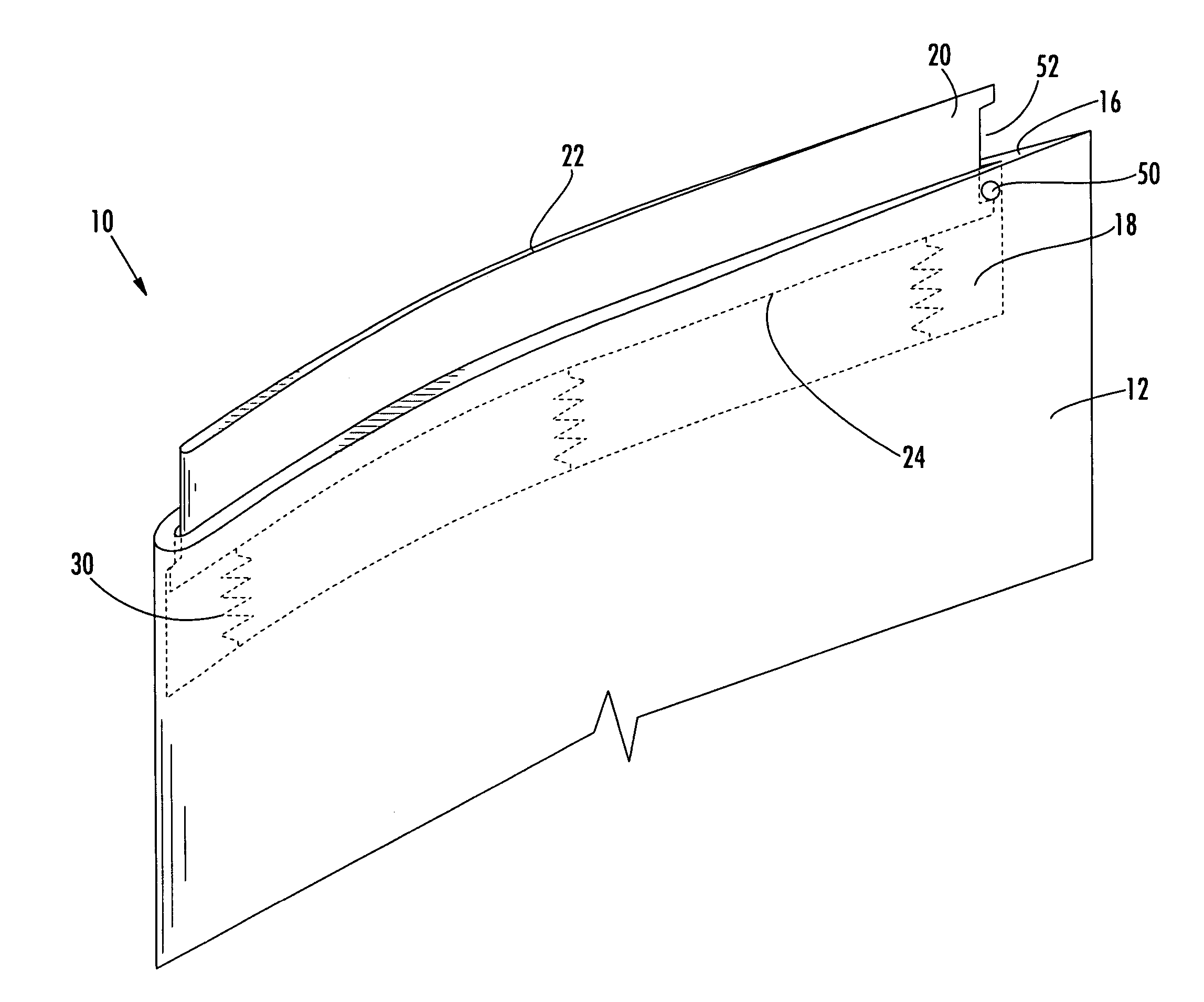
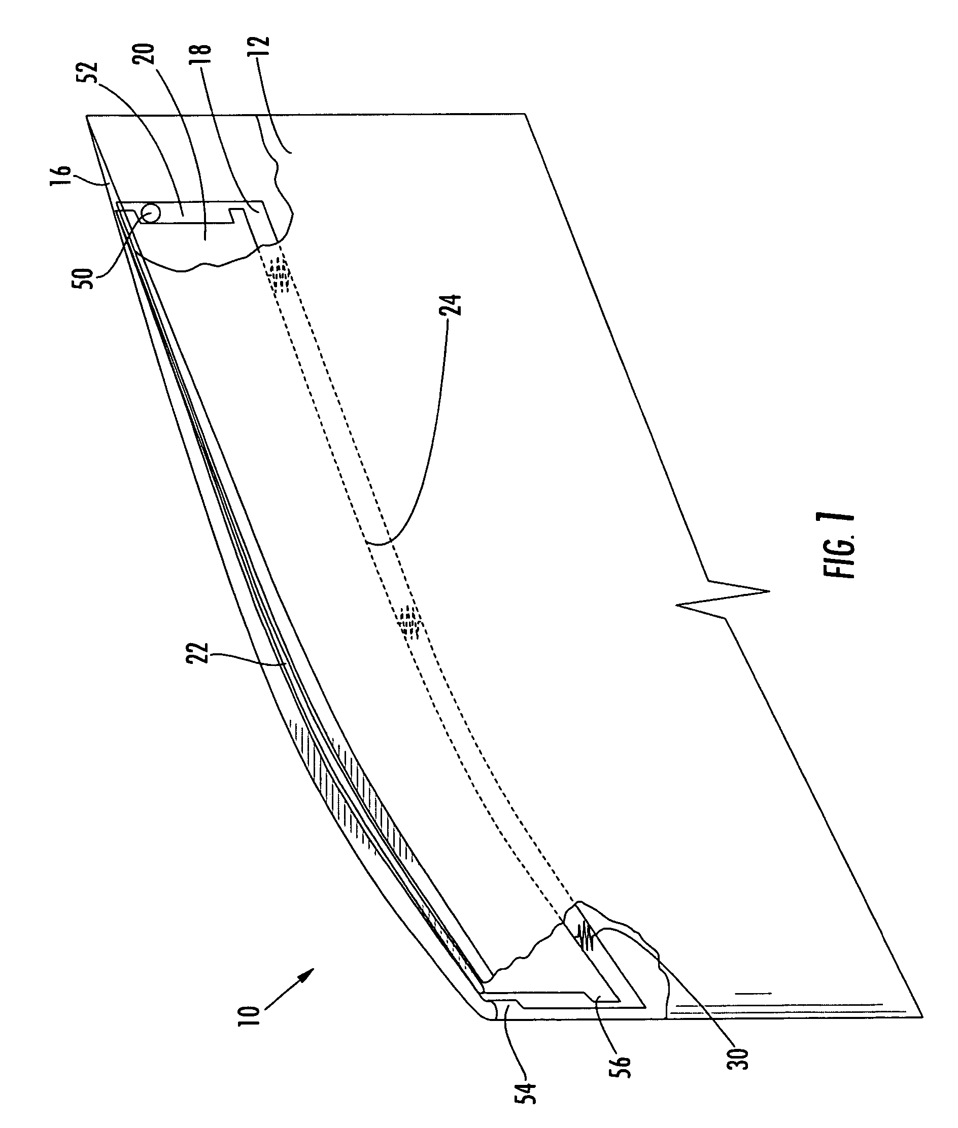
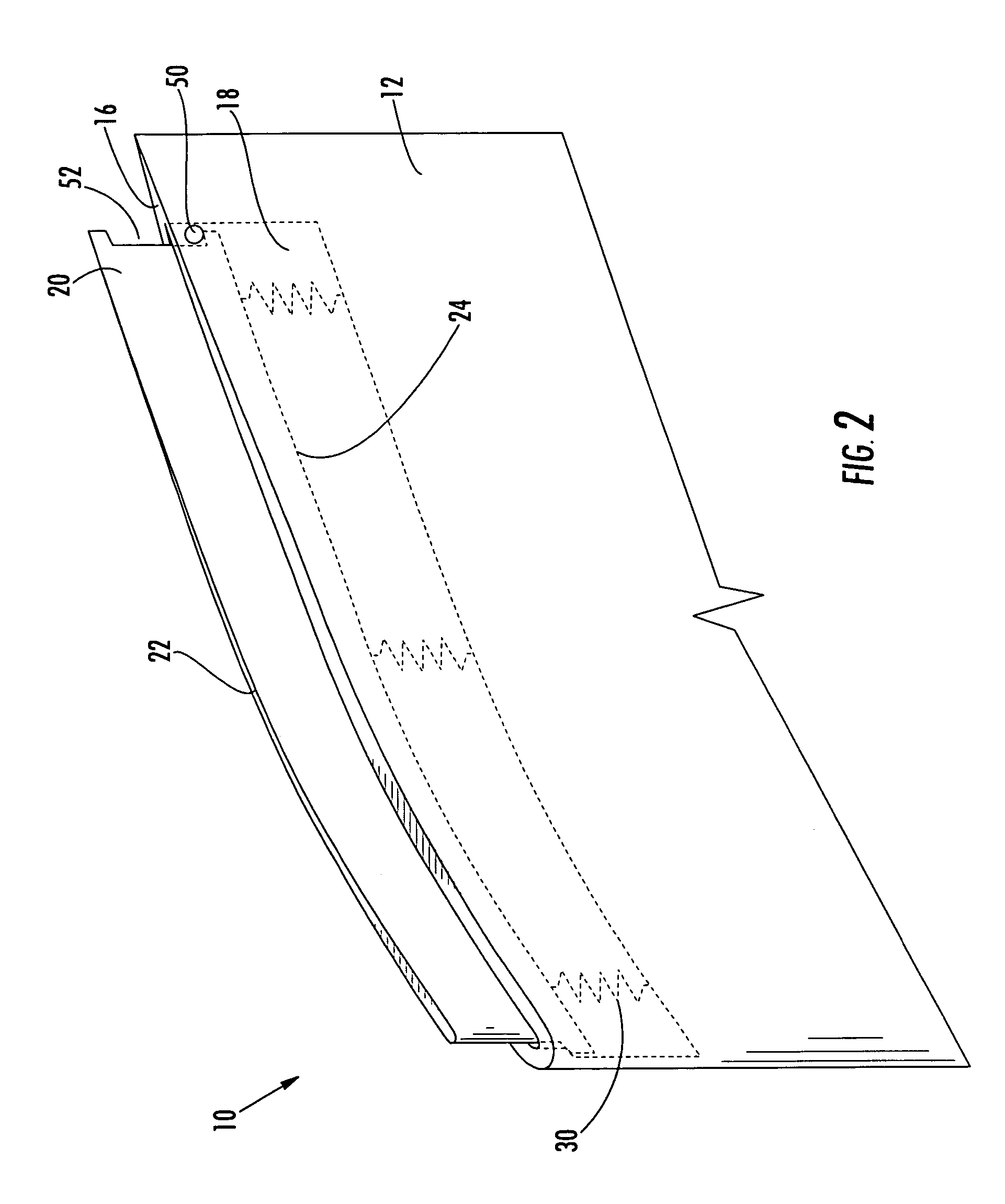
[0018]Aspects of the present invention improve upon prior blade tip management systems used in connection with turbine engines. Aspects of the present invention relate to airfoils having movable tips that permit relatively large clearances during non-normal operating conditions and relatively minimal clearances during normal operation of the engine, thereby enhancing the performance of the compressor.

[0019]Embodiments of the invention will be explained in the context of a turbine engine compressor system, but the detailed description is intended only as exemplary. Embodiments of the invention are shown in FIGS. 1–5, but the present invention is not limited to the illustrated structure or application.

[0020]Embodiments of a compressor blade assembly 10 according to aspects of the invention include an elongated airfoil 12. The airfoil 12 can have a radially proximal end 14 and a radially distal end 16. It should be noted that the dimensional terms used in connection with an airfoil 12 ...


PUM


Abstract

Aspects of the invention relate to a compressor system for a turbine engine that not only allows for larger compressor blade tip clearances as the engine passes through non-standard operating conditions, but also minimizes clearances during normal engine operation, thereby increasing efficiency of the compressor. The blade assembly can include an airfoil having a movable tip insert recessed within a pocket in the radially distal end of the airfoil. The tip insert can move radially outward from a predetermined recessed position to a predetermined extended position. An abutment surface can be provided within the pocket for engaging the tip insert and / or other associated components so as to limit the extension of the tip insert to the predetermined extended position such that the tip insert does not impinge on the stationary compressor structure and such that a spring operatively associated with the tip insert does not overextend its operational limits.

Description

FIELD OF THE INVENTION[0001]The invention relates in general to turbine engines and, more particularly, to a compressor system for increasing the power and efficiency of a turbine engine.BACKGROUND OF THE INVENTION[0002]The operational efficiency of a turbine engine is less than the theoretical maximum because of losses that occur along the flow path. One contributor to the losses is fluid leakage of across the tips of the compressor blades. In particular, the leakage occurs across a space between the tips of the rotating compressor blades and the surrounding stationary structure such as the casing. While minimal clearances are desired, it is critical to maintain a clearance between the blade tips and the stationary structure at all times. Tip rubbing can lead to substantial component damage, performance degradation, and extended outages.[0003]In the past, the problem of tip clearances has been approached by initially providing large tip clearances so that the tips do not rub during...

Claims


Application Information

Patent Timeline
Patent Type & Authority Patents(United States)
IPC IPC(8): F01D5/14F01D5/20F04D29/08F04D29/16
CPCF01D5/20F01D11/16F04D29/164
Inventor GARNER, CHAD MARCUS
Owner SIEMENS ENERGY INC
Why Eureka
Try Eureka