Scraper blade attachment apparatus and method with split pin

a technology of split pins and attachment apparatus, which is applied in the direction of rotors, machines/engines, chemical/physical processes, etc., can solve the problems of blades with blades that have tended to have relatively short attachment beams, and blades that fall out of pin receptacles

Active Publication Date: 2005-11-22
SPX FLOW INC
View PDF8 Cites 8 Cited by
  • Summary
  • Abstract
  • Description
  • Claims
  • Application Information

AI Technical Summary

Problems solved by technology

However, there can be some drawbacks to using longer blades and fewer pins when using the aforementioned prior art pin connection methods.
In the prior art, the blades have tended to have relatively short attachment beams due to shear and buckling failure modes.
Another disadvantage with at least some conventional pin and beam attachment systems has been that during assembly of the device, the blade may fall out of its pin receptacle depending on the manufacturing angle of the shaft, pin, and blade.

Method used


Image

  • Scraper blade attachment apparatus and method with split pin
  • Scraper blade attachment apparatus and method with split pin
  • Scraper blade attachment apparatus and method with split pin

Examples


Embodiment Construction

[0035]Preferred embodiments of the invention provide pivotal attachment of a blade to a drive shaft of a device such as a scraped surface heat exchanger. The invention will now be described with reference to the drawing figures, in which like reference numerals refer to like elements throughout.

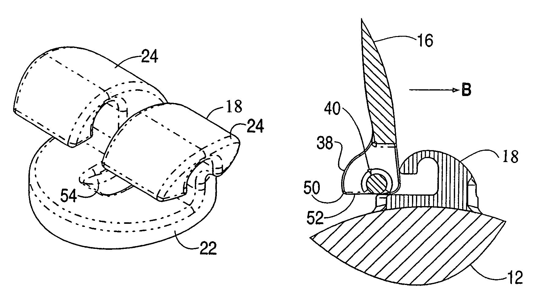
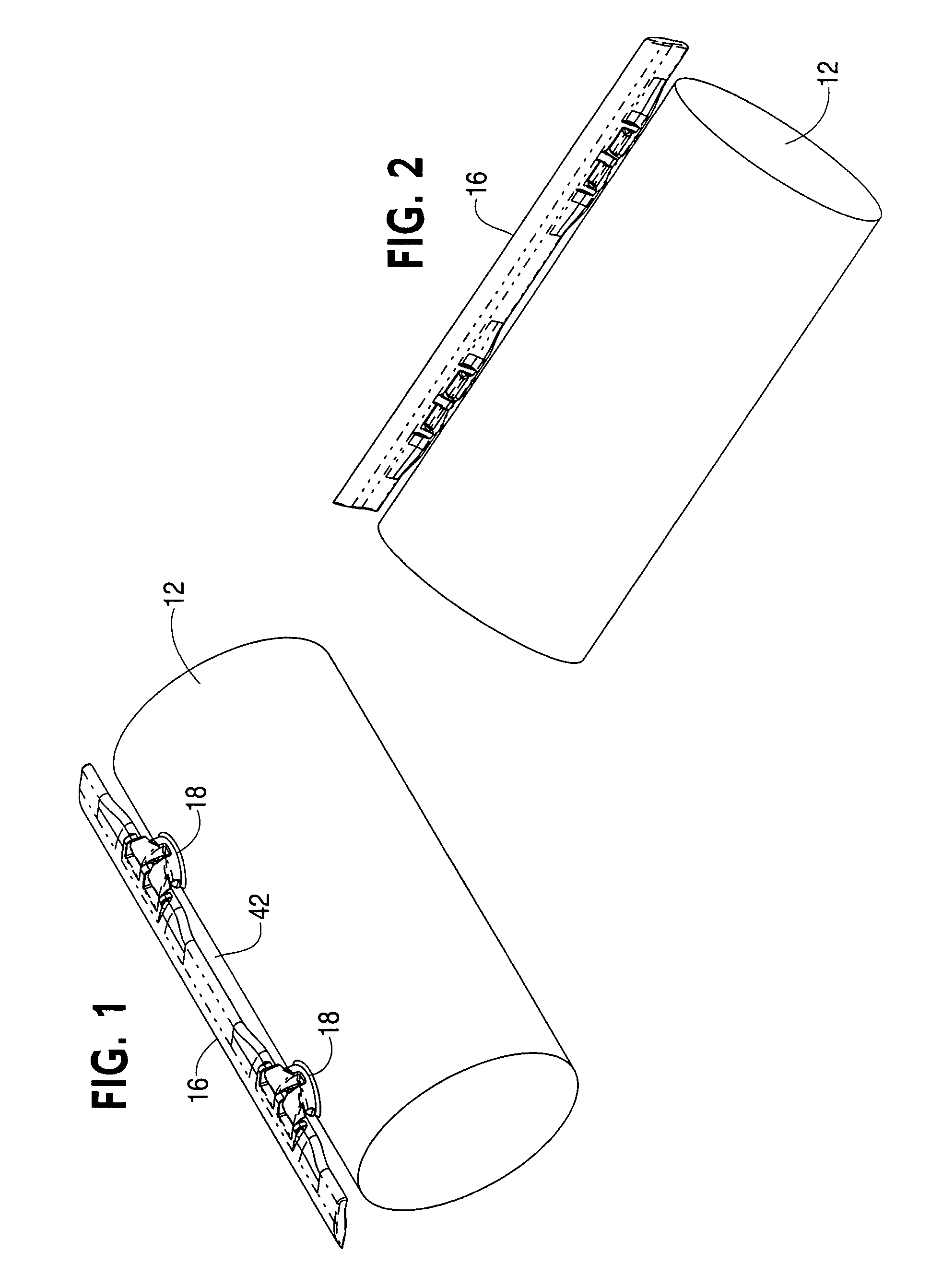
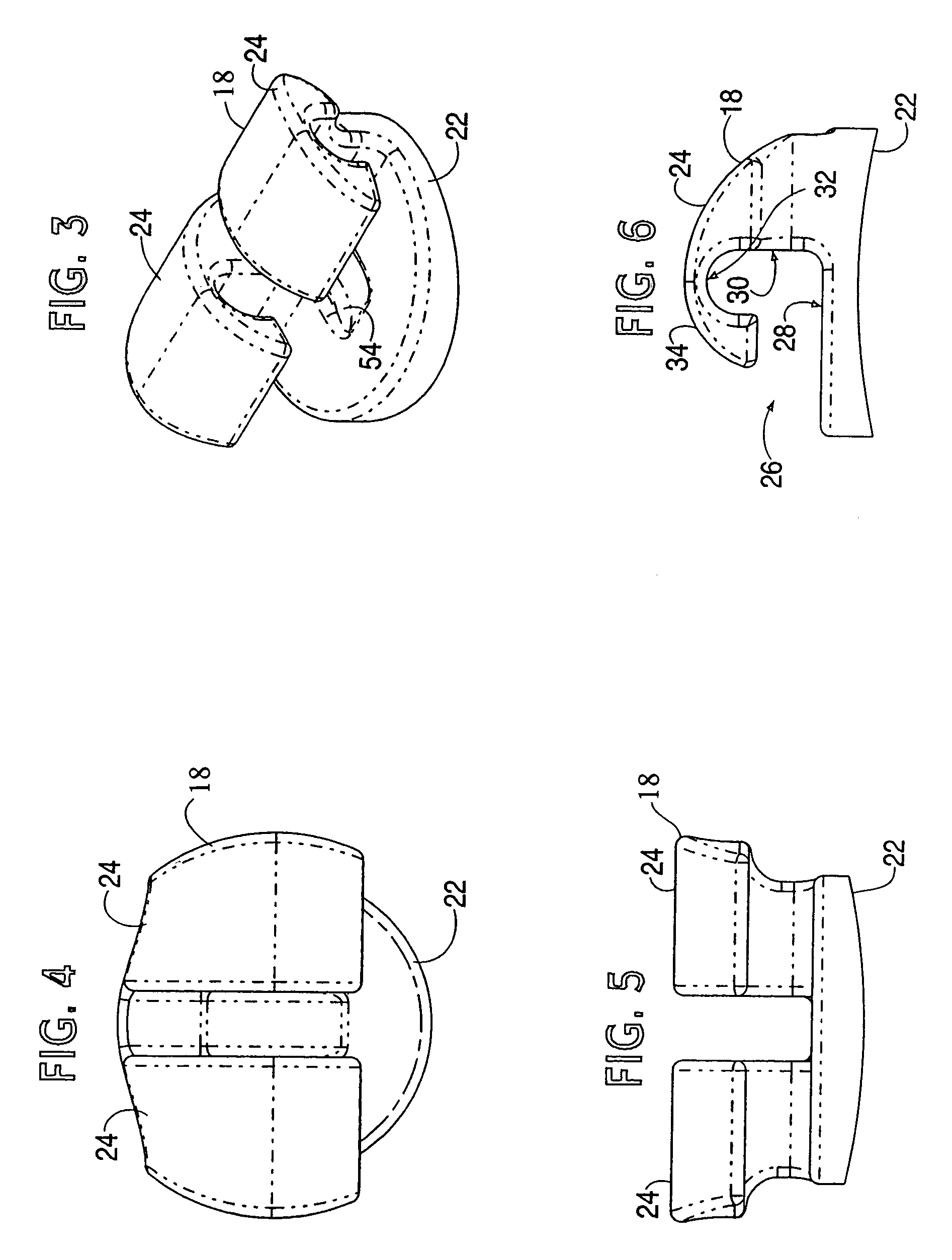
[0036]Turning to FIGS. 1, 2 and 11 initially, some components of a scraped surface heat exchanger are illustrated including a central drive shaft 12 which is powered for rotating motion, a stationary cylindrical outer housing tube 14 (seen in FIG. 11) which is surrounds either concentrically or eccentrically the drive shaft 12, and a blade 16 which is mounted to the shaft by two mounting pins 18. FIGS. 1 and 2 as well as FIGS. 7 and 10 of this description for convenience and simplicity illustrate a single blade 16 mounted to a portion of a shaft 12 of the scraped surface heat exchanger. However, there are preferably several blades 16 at even circumferential angles around the shaft 12 as illus...


PUM


Abstract

An attachment apparatus and method for interlocking attachment of a scraper blade with a drive shaft of a scraped surface heat exchanger includes a blade having dual attachment beams and a central locking member, and at least one pin having dual fingers each for interlocking with a respective attachment beam.

Description

FIELD OF THE INVENTION[0001]The invention pertains to the field of process equipment. More particularly, the invention pertains to the attachment of blades to a rotating drive shaft, such as for example in scraped surface heat exchangers.BACKGROUND OF THE INVENTION[0002]Scraped surface heat exchangers are a type of mixing apparatus well known in industry. Scraped surface heat exchangers generally feature an outer cylindrical housing tube and a central rotatable drive shaft disposed in the center of the outer housing tube. An annular space is provided between the central drive shaft and the outer housing tube, and material is forced from one end of the scraped surface heat exchanger through the annular space between the tubes.[0003]In general, the material enters the space between the tubes near one end of the scraped surface heat exchanger and travels longitudinally along the scraped surface heat exchanger and exits near the other end of the scraped surface heat exchanger. During th...

Claims


Application Information

Patent Timeline
Patent Type & Authority Patents(United States)
IPC IPC(8): B01F15/00B01F7/00F28F19/00
CPCB01F7/00208F28F19/008B01F7/00033B01F27/053B01F27/091
Inventor HARDY, BENJAMINNORMAN, DREW VAN
Owner SPX FLOW INC
Why Eureka
Try Eureka