Syringe pumps

a technology of syringe and pump head, which is applied in the direction of piston pump, positive displacement liquid engine, instruments, etc., can solve the problem that the head actuator may trap the user's finger or other objects

Inactive Publication Date: 2005-11-22
SMITHS GRP PLC
View PDF10 Cites 34 Cited by
  • Summary
  • Abstract
  • Description
  • Claims
  • Application Information

AI Technical Summary

Benefits of technology

[0003]It is an object of the present invention to provi

Problems solved by technology

There is a risk, when the head actuator is being moved back to its loading position, that the hea

Method used


Image

  • Syringe pumps
  • Syringe pumps
  • Syringe pumps

Examples


Embodiment Construction

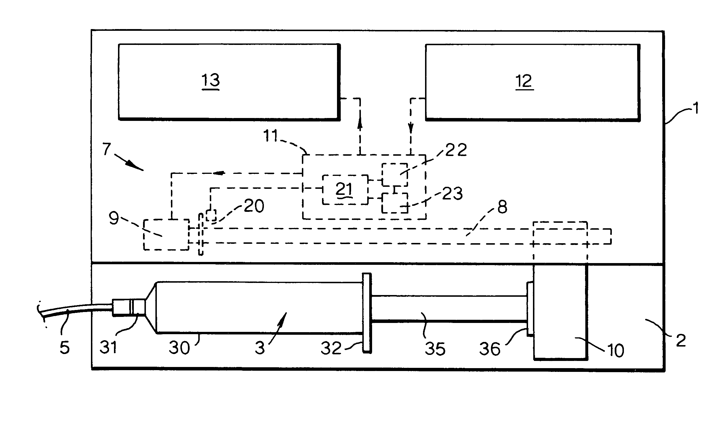
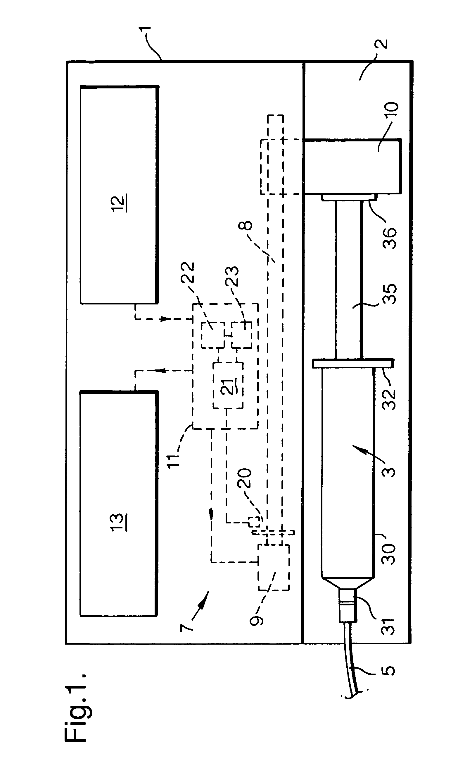
[0013]The pump includes an outer housing 1 with a recess 2 on its front surface shaped to receive a syringe 3 of conventional kind. The syringe 3 has a cylindrical barrel 30 with an outlet or nose 31 at its forward end and a flange or ear 32 at its rear end. The nose 31 is connected to an infusion line 5 so that a medication liquid in the syringe 3 can be dispensed to a patient via the infusion line, by pushing in the plunger 35.

[0014]The pump has a drive mechanism 7, including a leadscrew 8 driven by an electric stepper motor 9. A plunger head actuator or retainer mechanism 10 engages the head 36 of the plunger 35 and is movable along the leadscrew 8 as it rotates, so as to move the plunger along the barrel 30. Further details of the plunger head actuator are given in GB2352637. The motor 9 is driven by a control unit 11, which receives inputs from a keypad 12, or other user input means, and various sensors (not shown). The control unit 11 also provides an output to a display panel...


PUM


Abstract

A syringe pump has a motor rotating a leadscrew to drive a plunger head actuator along it. The head actuator engages the plunger of a syringe and moves the plunger along the syringe barrel to dispense medication. An optical encoder mounted on the leadscrew is rotated by the motor to produce a pulse output. A control unit times the interval between the pulses and compares these timings with a stored value representative of a predetermined multiple of the minimum time. If the head actuator is obstructed, the speed of rotation of the motor is slowed and the time interval between pulses rises. When this exceeds the stored value, the control unit stops the drive to the head actuator and generates an alarm.

Description

BACKGROUND OF THE INVENTION[0001]This invention relates to syringe pumps.[0002]Syringe pumps are used to supply medication to a patient from a pre-filled syringe via an infusion line. The syringe pump applies a force to the plunger of the syringe to drive medication into the infusion line at a controlled rate. The head of the plunger is engaged by a plunger head actuator that is movable along a leadscrew extending parallel to the axis of the syringe. The head actuator is movable from an extreme position at one end of the pump, where it allows the largest syringe to be loaded into the pump with its plunger fully extended, to an extreme position at the opposite end of the pump, where it fully depresses the plunger of the smallest syringe. There is a risk, when the head actuator is being moved back to its loading position, that the head actuator may trap the user's finger or other objects between the actuator and the pump housing.BRIEF SUMMARY OF THE INVENTION[0003]It is an object of t...

Claims


Application Information

Patent Timeline
IPC IPC(8): A61M5/145A61M5/168A61M5/172A61M5/142F04B49/10B05C11/10F04B9/02
CPCA61M5/14546A61M5/16831A61M5/1456A61M5/16854A61M5/172A61M2205/3306
Inventor TRIBE, ROBERT JAMES
Owner SMITHS GRP PLC
Why Eureka
Try Eureka