Device and method for preparing a space between adjacent vertebrae to receive an insert

Inactive Publication Date: 2005-11-22
WARSAW ORTHOPEDIC INC
View PDF33 Cites 128 Cited by
  • Summary
  • Abstract
  • Description
  • Claims
  • Application Information

AI Technical Summary

Benefits of technology

[0076]In the instance where the abrading element has one abrading surface, the opposite surface of the abrading element, or the opposite surface of the mounting member, may be specifically designed to be non-abrading to the opposed adjacent vertebral end plate. Such a non-abrading surface may be designed to provide a mechanical advantage (such as achieved with a fulcrum) to allow the surgeon to increase the pressure of the abrading surface against the end plate being worked on, and, further, may be curved so as to be centering within the disc space by contact with a vertebral surface.
[0077]While the preferred embodiment of the present invention is discussed and disclosed herein with respect to creating a space between adjacent vertebrae in the spine, the present invention is not limited to a device for creating a space between adjacent vertebrae, but can also be used in other portions of the body where it is desirable to place an insert between adjacent bone structures. Furthermore, and as alluded to above, an embodiment of the

Problems solved by technology

Such inserts may or may not be designed to promote fusion of the adjacent vertebral bodies.
Such a surgical procedure necessarily results in the loss of the hardest and strongest bone tissue of the vertebrae—the end plate—and thereby robs the vertebrae of that portion of its structure best suited to absorbing and supporting the loads placed on the spine by everyday activity.
In instances where the surgeon has not been able to form the appropriatel

Method used


Image

  • Device and method for preparing a space between adjacent vertebrae to receive an insert
  • Device and method for preparing a space between adjacent vertebrae to receive an insert
  • Device and method for preparing a space between adjacent vertebrae to receive an insert

Examples


first embodiment

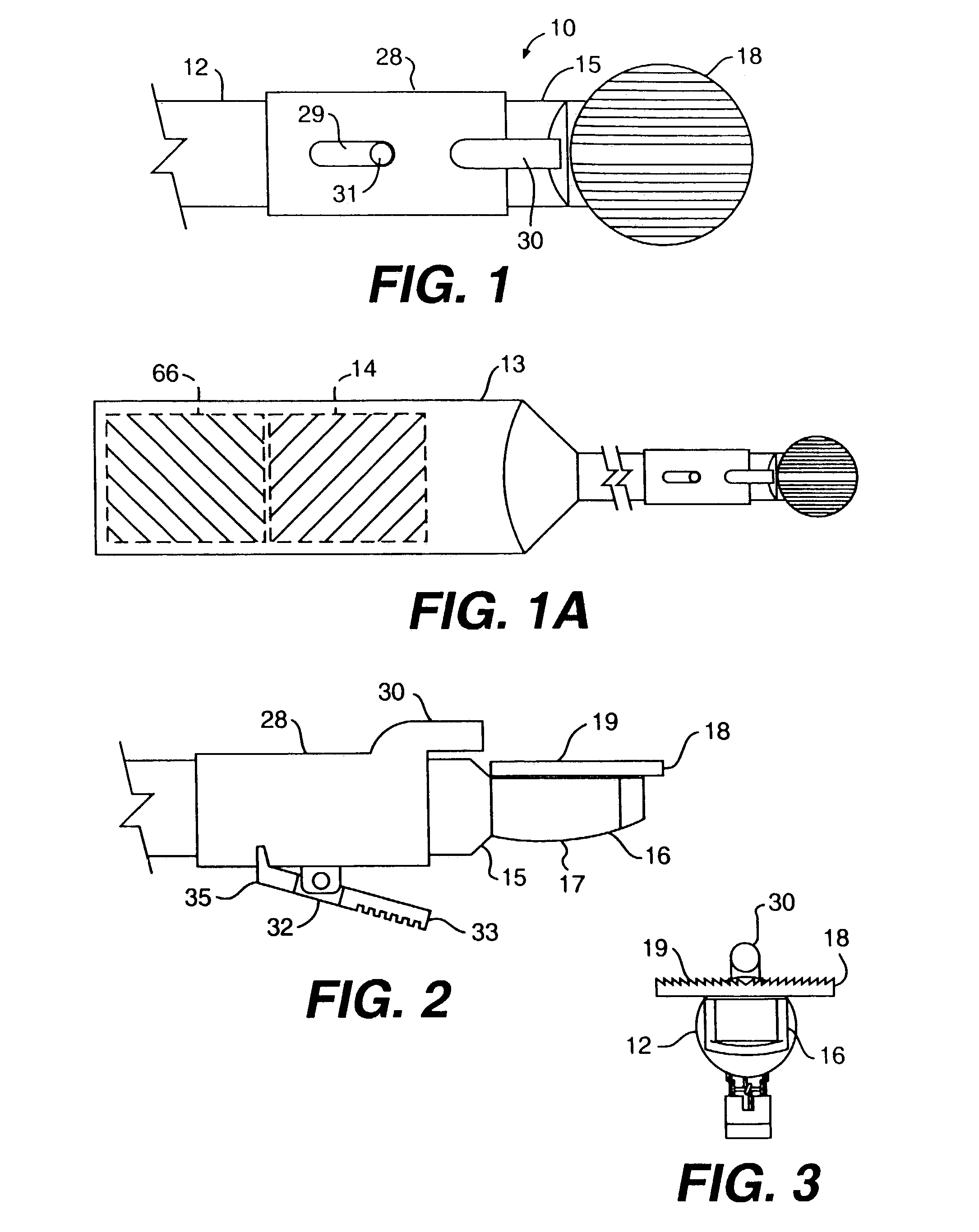
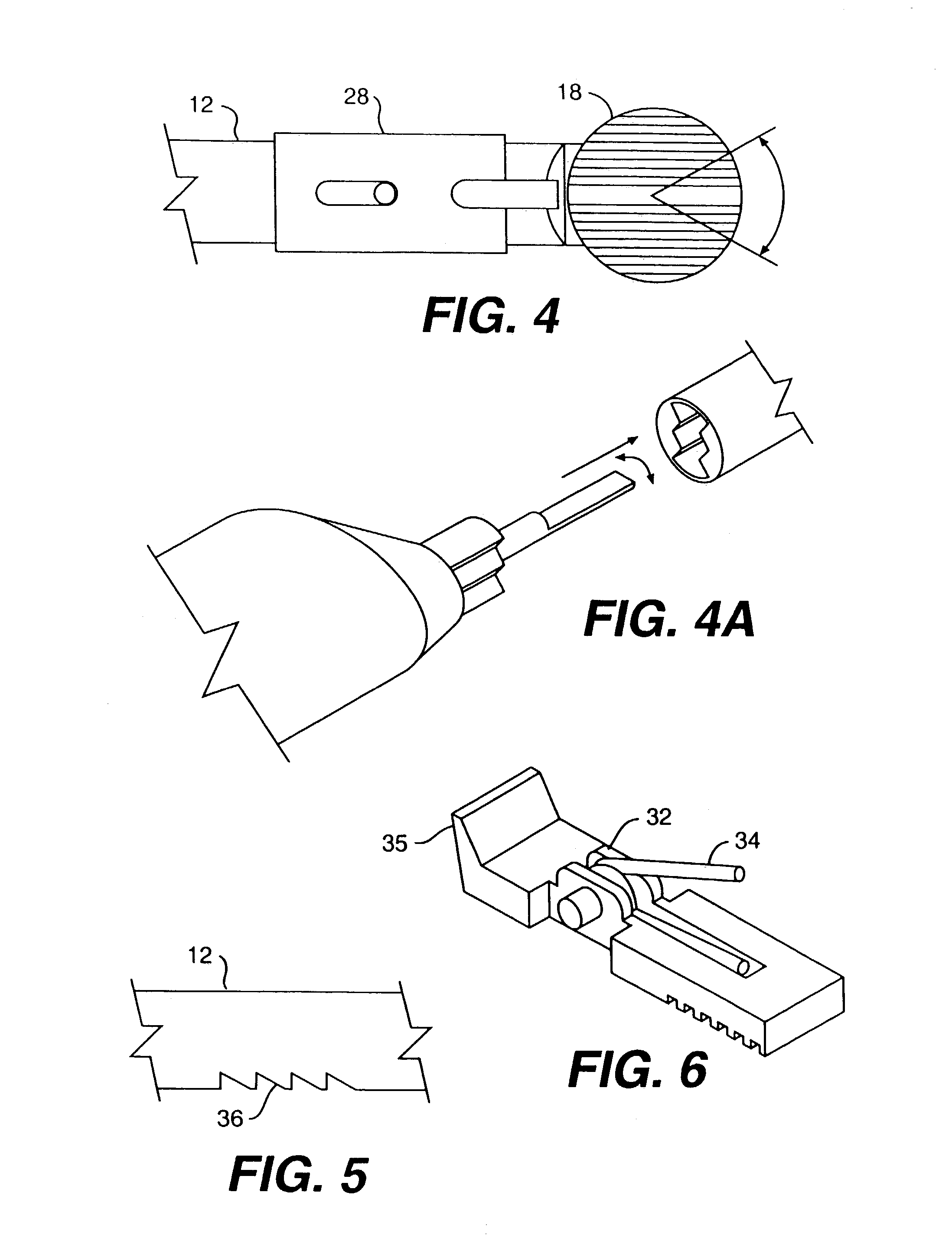
[0079]With reference to FIGS. 1 and 1A, the present invention comprises a disc space preparation device generally referred to by numeral 10. Device 10 includes a shaft 12 and a handle 13. Handle 13 may be formed with any number of known shapes designed to make the surgeon's grip on the handle more secure or comfortable. Similarly, handle 13 may include a soft rubber covering or may be formed, at least partially, of a material designed to promote a secure grip of the surgeon's hand on the handle. Those of ordinary skill in the art will recognize the many types of surface configurations or materials of which the handle can be made to achieve these goals.

[0080]With continued reference to FIGS. 1 and 1A, disposed within handle 13 is a drive mechanism diagrammatically depicted by box 14. Although in the embodiment of the device shown in FIGS. 1 and 1A the drive mechanism 14 is disposed within handle 13, it need not be disposed in the handle. The drive mechanism may be disposed completely...

second embodiment

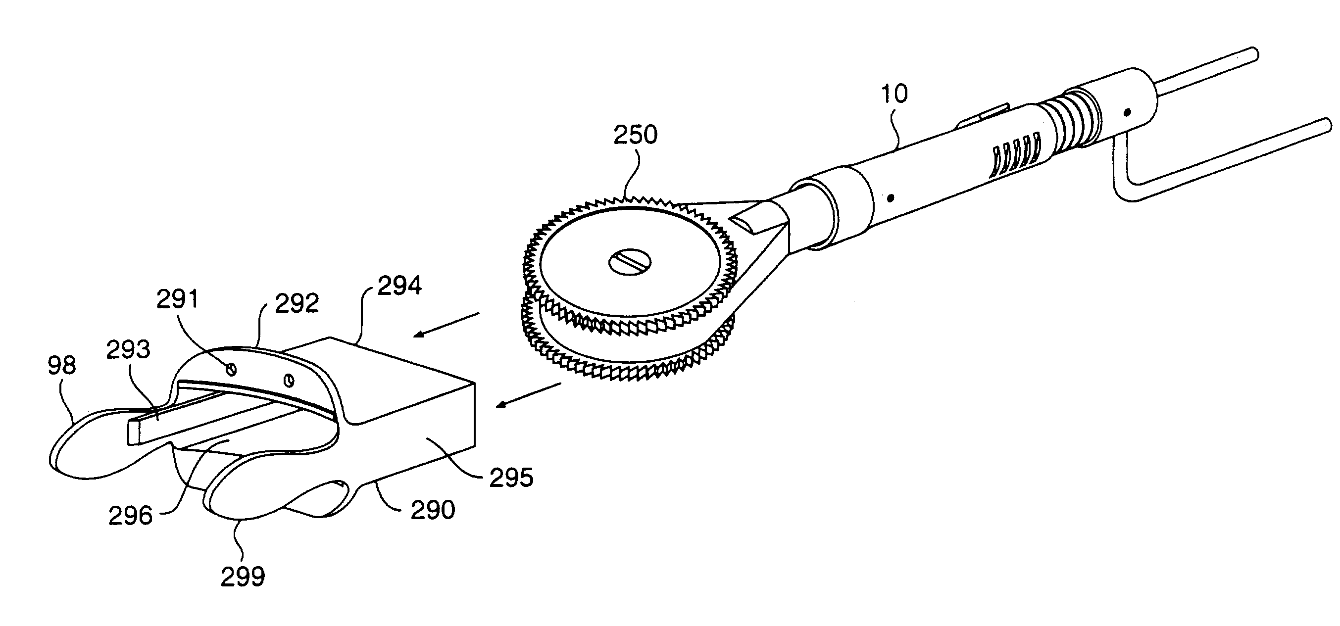
[0107]FIGS. 25A and 25B show an alternative to the present invention, wherein abrading element 250 includes two abrading surfaces, upper abrading surface 252 and lower abrading surface 254, and abrading surfaces 252 and 254 are configured with a sharpened leading edge. FIG. 25A is a perspective view of such a device and FIG. 25B is a top view. In this embodiment, abrading element 250 includes two disc-shaped members, 256 and 258, that are removably mounted on the distal end of the device by a recessed screw 147 and screw shaft 148 as described above. Abrading surface 252 is formed on the edge of disc member 256, and abrading surface 254 is formed on the edge of disc member 258. The mounting facilitates removing disc-shaped members 256 and 258 to replace them with other disc-shaped members of similar or alternative abrading surface design. Brace 255 prevents rotation of shaft 12 during use of the device.

[0108]Alternatively, abrading surfaces 252 and 254 may be manufactured separately...


PUM


Abstract

A device and method for use in a human spine to prepare a space between adjacent vertebral bodies and into the vertebral end plates to receive an implantable insert. The device includes a handle, a shaft, and a mounting member at one end of the shaft. An abrading element is mounted on the mounting member and is coupled to a drive mechanism. The drive mechanism is operable to move the abrading element in at least one degree of freedom to create surfaces having predetermined contours in the end plates of the adjacent vertebral bodies.

Description

RELATED APPLICATIONS[0001]This application is a continuation of application Ser. No. 09 / 663,311, filed Sep. 15, 2000, now U.S. Pat. No. 6,517,544, which is a continuation and claims priority to International Application No. PCT / US99 / 12890, filed Jun. 9, 1999, which is hereby incorporated by reference.FIELD OF THE INVENTION[0002]The present invention relates to a device for insertion into a disc space between adjacent vertebral bodies in the human spine, and a method of working on those portions of the vertebral bodies adjacent that disc space to remove bone material and thereby access vascular bone. The device and associated method forms a surface on each of the vertebral body surfaces that are adjacent the intervertebral disc space, either sequentially, or in an alternative embodiment, simultaneously. The formed surface(s) have a shape and a contour corresponding to an interbody spinal insert to be implanted in the disc space.BACKGROUND OF THE INVENTION[0003]Inserts for placement b...

Claims


Application Information

Patent Timeline
IPC IPC(8): A61B17/17A61B17/16A61B17/88A61B17/32A61B19/00A61F2/46A61F2/44A61B17/00A61M1/00A61B17/02A61B17/70A61B17/86
CPCA61B17/1659A61B17/1671A61B17/1757A61B17/864A61B17/8685A61B17/1624A61B17/1628A61B17/1662A61B17/320068A61B17/7041A61B2017/0046A61B2017/00477A61B2017/00544A61B2017/00734A61B2017/0256A61B2017/320004A61B2017/320084A61B2019/303A61B2217/005A61B2217/007A61F2/442A61F2/4611A61B2090/033A61B2017/32007
Inventor MICHELSON, GARY K.
Owner WARSAW ORTHOPEDIC INC
Why Eureka
Try Eureka