Anti-rotation tool

a tool and anti-rotation technology, applied in the field of anti-rotation tools, can solve the problems of loss of pump or tubing string, and achieve the effect of preventing overextension of the jaw during assembly, limiting the maximum rotation of the jaw, and limiting the effective diameter of the tool

Inactive Publication Date: 2005-11-29
TESSIER LYNN P +2
View PDF27 Cites 17 Cited by
  • Summary
  • Abstract
  • Description
  • Claims
  • Application Information

AI Technical Summary

Benefits of technology

[0006]A simplified anti-rotation tool is provided, having only one jaw as a moving part but which both prevents rotation and stabilizes that to which it is connected. In simplistic terms, the tool connects to a progressive cavity (PC) pump or other downhole tool. Upon rotation of the tool in one direction a jaw, which is biased outwardly from the tool housing, engages the casing wall to arrest tool rotation. This action causes the tool housing to move oppositely and come to rest against the casing opposing the jaw. The tool housing and the downhole tool are thereby restrained and stabilized by the casing wall.
[0011]Preferably, overextension of the jaw during assembly is prevented using cooperating stops in the jaw and the housing. In a broad aspect, a downhole tool comprises a tubular housing for suspension in a wellbore casing and having a wall which engages the wellbore casing and having at least one end for threaded connection to the downhole tool, a jaw having a radial tip and which is rotatable along an axis along a base of the jaw and along a hinge on wall of the housing opposing the casing engaging wall for varying the effective diameter of the tool, a first stop formed on the base of the jaw, and a second stop formed in the wall of the housing at the hinge. The first and second stops co-operate so as to limit maximum rotation of the jaw, while permiting the effective diameter of the tool to increase to a diameter greater than the casing.

Problems solved by technology

Large reaction or rotor rotational forces can cause the tubing or PC pump stator to unthread, resulting in loss of the pump or tubing string.
Further, the eccentric rotation of the PC Pump rotor imposes cyclical motion of the PC Pump stator, which in many cases is supported or restrained solely by the tool's slips.

Method used


Image

  • Anti-rotation tool
  • Anti-rotation tool
  • Anti-rotation tool

Examples


first embodiment

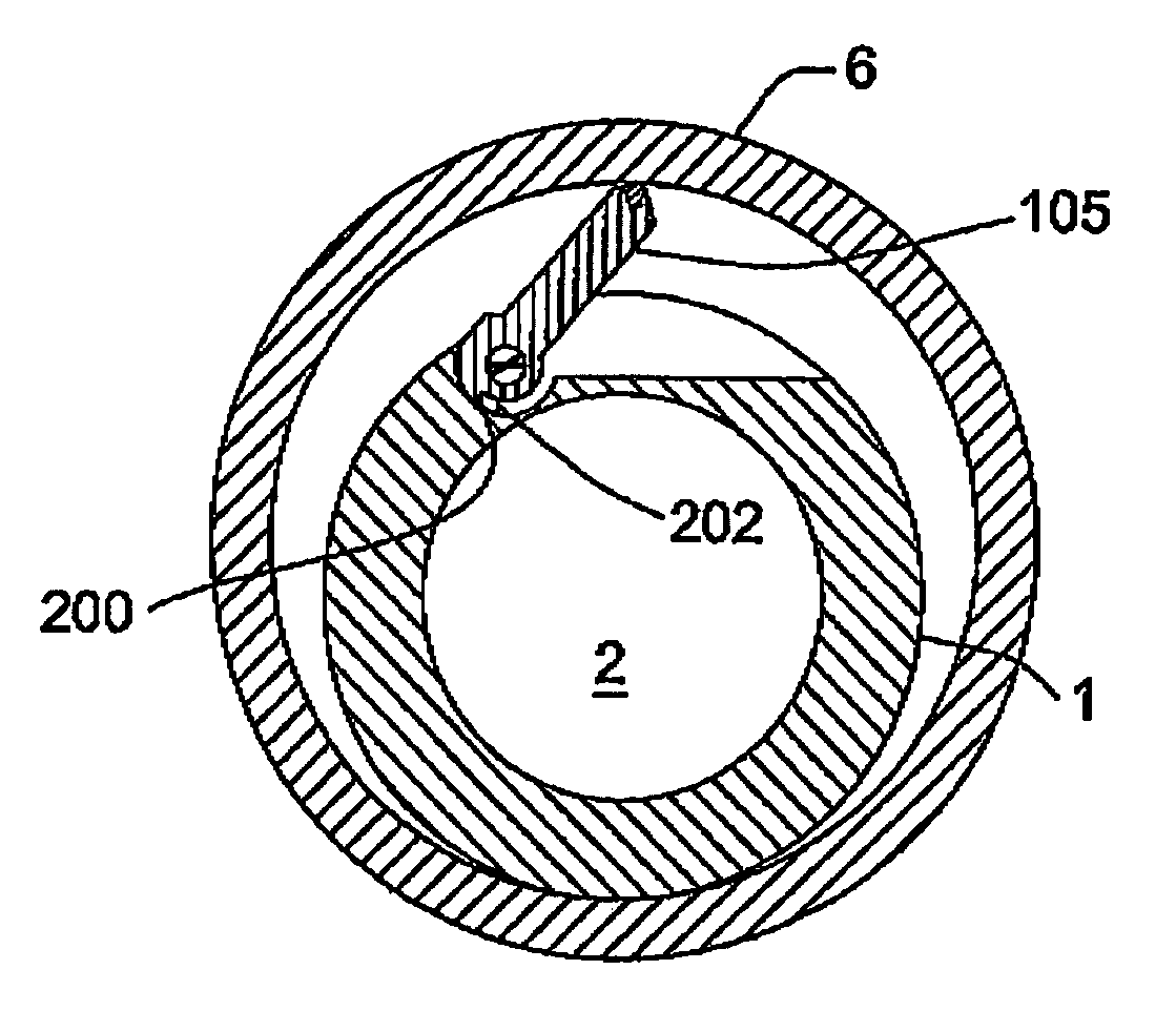
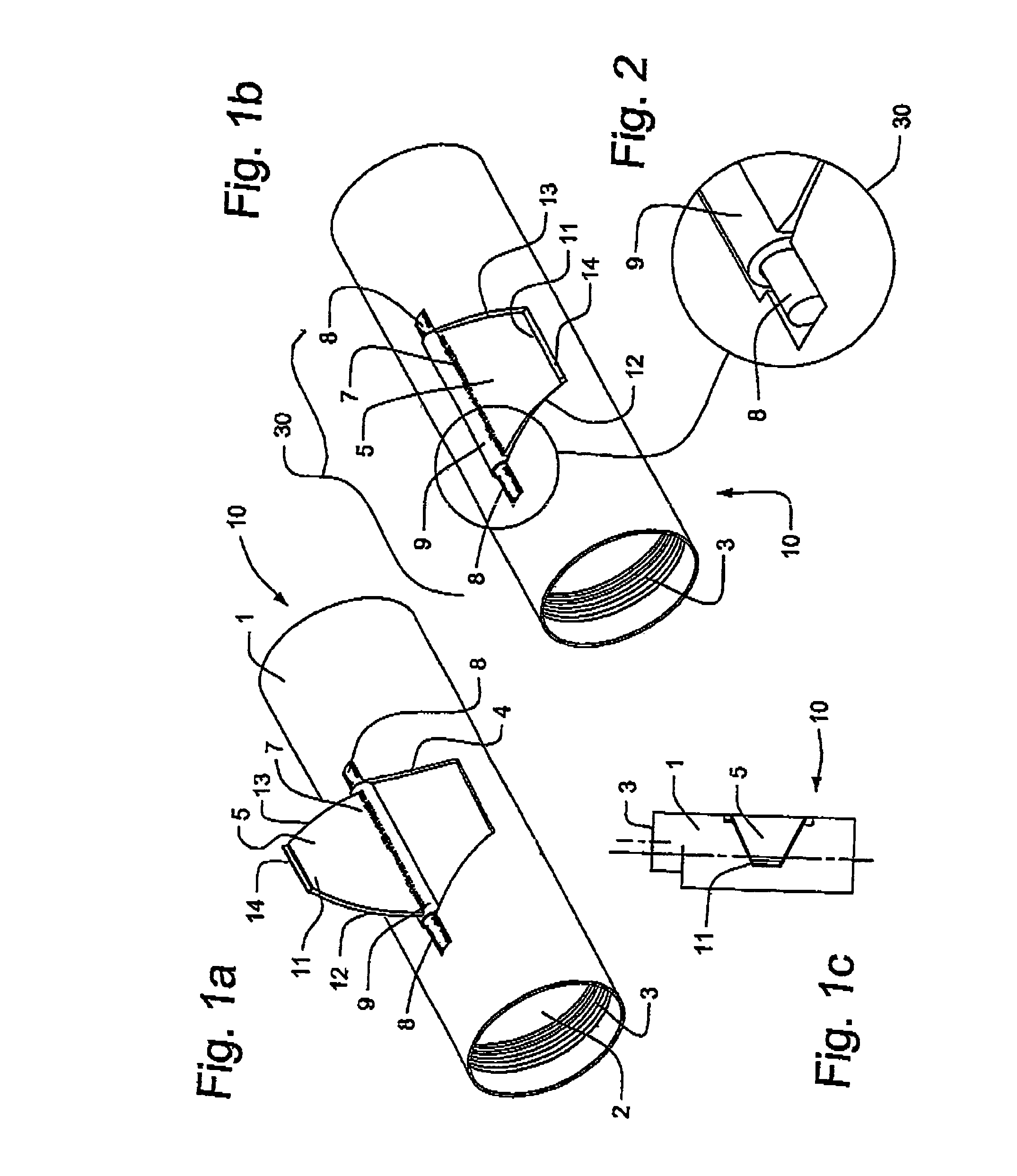
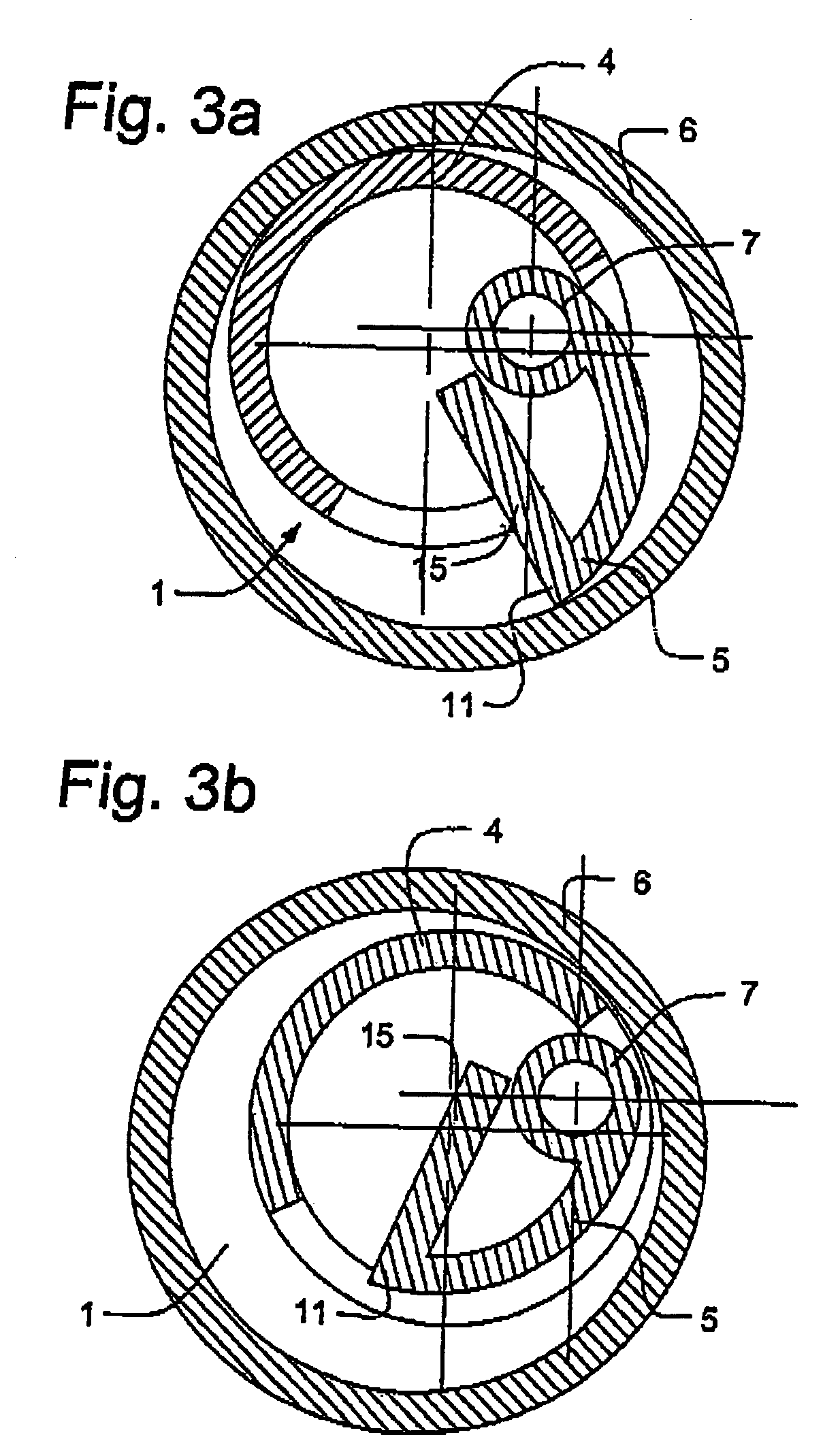
[0033]More particularly, in the first embodiment and having reference to FIGS. 1a, 1b, 3a and 3b a portion of the housing wall 4 is cut through to the bore 2 to form a trapezoidal flap or jaw 5. The jaw 5 has an arcuate profile, as viewed in cross-section, which corresponds to the curvature of the housing wall 4. Accordingly, when stowed, the jaw 5 projects minimally from the tubular housing 1 and avoids interfering with obstructions while running into the casing 6 (FIG. 3b).

[0034]Referring to FIGS. 1a–2, the jaw 5 is pivoted to the housing 1 along a circumferential edge 7 at hinge 30. The jaw 5 has a radial tip edge 11.

[0035]Hinge 30 comprises tubing 9 welded to the hinge edge 7 with a pin 8 inserted therethrough. Pin 8 is welded to the housing wall 4 at its ends. In a mirrored and optional arrangement (not shown), the jaw's hinge edge 7 has axially projecting pins and the housing wall is formed with two corresponding and small tubular sockets for pinning the pins to the housing an...

second embodiment

[0043]Referring back to FIG. 1c, in an optional second embodiment, the threaded end 3 can be formed off-center to the axis of the housing 1, so that when the radial tip 11 engages the casing 6, the axis of the threaded end 3 is closer to the center of the casing 6 than is the axis of the housing 1. This option is useful if the PC Pump or other downhole tool requires centralization.

[0044]In the first and second embodiment, the jaw 5 is conveniently formed of the housing wall 4, however, this also opens the bore 2 to the wellbore. If the tool 10 threaded to the bottom of a PC Pump, this opening of the bore 2 is usually irrelevant. However, where the bore 2 must support differential pressure, such as when the PC Pump suction is through a long fluid conducting tailpiece, or the tool 10 is secured to the top of the PC Pump and must pass pressurized fluids, the bore 2 must remain sealed.

third embodiment

[0045]Accordingly, and having reference to FIGS. 4–5b, in a third embodiment, the housing wall 4 is not interfered with so that the bore 2 remains separate from the wellbore. This is achieved by mounting the jaw 5 external to the housing 1. The profile of jaw 5 conforms to the housing wall 4 so as to maintain as low a profile as possible when stowed (FIG. 5b).

[0046]More specifically as shown in FIG. 4, as was the case in the first embodiment, the profile of the jaw 5 corresponds to the profile of the housing wall 4. In this embodiment however, the jaw 5 is pivoted along its circumferential edge 7 at a piano-type hinge 30 mounted external to the housing wall 4. Corresponding sockets 9 are formed through the circumferential edge of the jaw and the hinge 30. Pin 8 is inserted through the sockets 9. A carbide insert 14 is fitted to the radial tip edge 11 of the jaw 5.

[0047]In operation, as shown in FIG. 5a, if the tool 1 is rotated clockwise as viewed from the top, the radial tip edge 1...


PUM


Abstract

A tool is provided for preventing the rotation of a downhole tool or rotary pump stator, the tool comprising a tubular housing and a jaw which is biased radially outwardly from the tool to engage the casing wall for arresting tool rotation and providing significant stabilization of a rotary pump. In doing so, the tool housing moves oppositely to rest against the casing opposite the jaw. The tool housing and the downhole tool are thereby restrained and stabilized by the casing wall. The tool's jaw is released by opposite tool rotation. Preferably, the jaw is biased outwardly from the tool housing to a casing-engaging position by a torsional member, housed along the axis of the hinge of the jaw. The tool is released from the casing by opposite tool rotation which increasingly compresses the jaw toward the housing, twisting the torsional member into torsion, which then acts to urge the jaw outwardly again. Overextension of the jaw during assembly is prevented using cooperating stops in the jaw and the housing.

Description

CROSS REFERENCE TO RELATED APPLICATION[0001]This application is a continuation-in-part of pending U.S. patent application Ser. No. 09 / 962,105 filed on Sep. 26, 2001, now U.S. Pat. No. 6,681,853, filed as a CIP of U.S. patent application Ser. No. 09 / 517,555 filed Mar. 2, 2000, now U.S. Pat. No. 6,318,462 and issued Nov. 20, 2001, the entirety of which is incorporated herein by reference.FIELD OF THE INVENTION[0002]The invention relates to a tool for preventing rotation of a tubing string or progressive cavity pump in the bore of a casing string.BACKGROUND OF THE INVENTION[0003]Oil is often pumped from a subterranean reservoir using a progressive cavity (PC) pump. The stator of the PC pump is threaded onto the bottom of a long assembled string of sectional tubing. A rod string extends downhole and drives the PC pump rotor. Large reaction or rotor rotational forces can cause the tubing or PC pump stator to unthread, resulting in loss of the pump or tubing string.[0004]Anti-rotation too...

Claims


Application Information

Patent Timeline
Patent Type & Authority Patents(United States)
IPC IPC(8): E21B23/01
CPCE21B23/01
Inventor DOYLE, JOHN P.TESSIER, LYNN P.WEBER, JAMES L.
Owner TESSIER LYNN P
Why Eureka
Try Eureka