Arteriostenosis diagnosing apparatus

a technology of arteriostenosis and diagnostic equipment, applied in the field of arteriostenosis diagnostic equipment, can solve the problems of high possibility and abnormal first velocity information, and achieve the effect of reducing the risk of recurren

Inactive Publication Date: 2005-11-29
OMRON HEALTHCARE CO LTD
View PDF9 Cites 10 Cited by
  • Summary
  • Abstract
  • Description
  • Claims
  • Application Information

AI Technical Summary

Benefits of technology

[0009]It is therefore an object of the present invention to provide an arteriostenosis diagnosing apparatus which can more reliably find arteriostenosis of a living subject.
[0012]There are some cases where, because not only arteriostenosis and but also calcification progress in the inferior limb from which the inferior limb blood pressure used to determine the inferior and superior limb blood pressure index is measured, the blood pressure index does not fall in the prescribed abnormal index range, i.e., falls in a prescribed normal or advisory range, and the first pulse wave velocity related information obtained from the first interval whose one end is defined by the first measuring point where the inferior limb blood pressure is measured and which includes the upstream portion of the inferior limb that is located upstream of the first measuring point falls in the prescribed normal information range. Even in those cases, if the second pulse wave velocity related information obtained from the second interval which does not include any portions of the inferior limb falls in the prescribed abnormal information range, the arteriostenosis judging means judges that there are some possibilities that the inferior limb may have arteriostenosis. Thus, the present apparatus can more reliably find the arteriostenosis of the inferior limb.

Problems solved by technology

More specifically described, calcification of artery is considerably systemic and accordingly, if the second pulse wave velocity related information is abnormal, then there is a high possibility that the first velocity related information may also be abnormal.

Method used


Image

  • Arteriostenosis diagnosing apparatus
  • Arteriostenosis diagnosing apparatus
  • Arteriostenosis diagnosing apparatus

Examples


Embodiment Construction

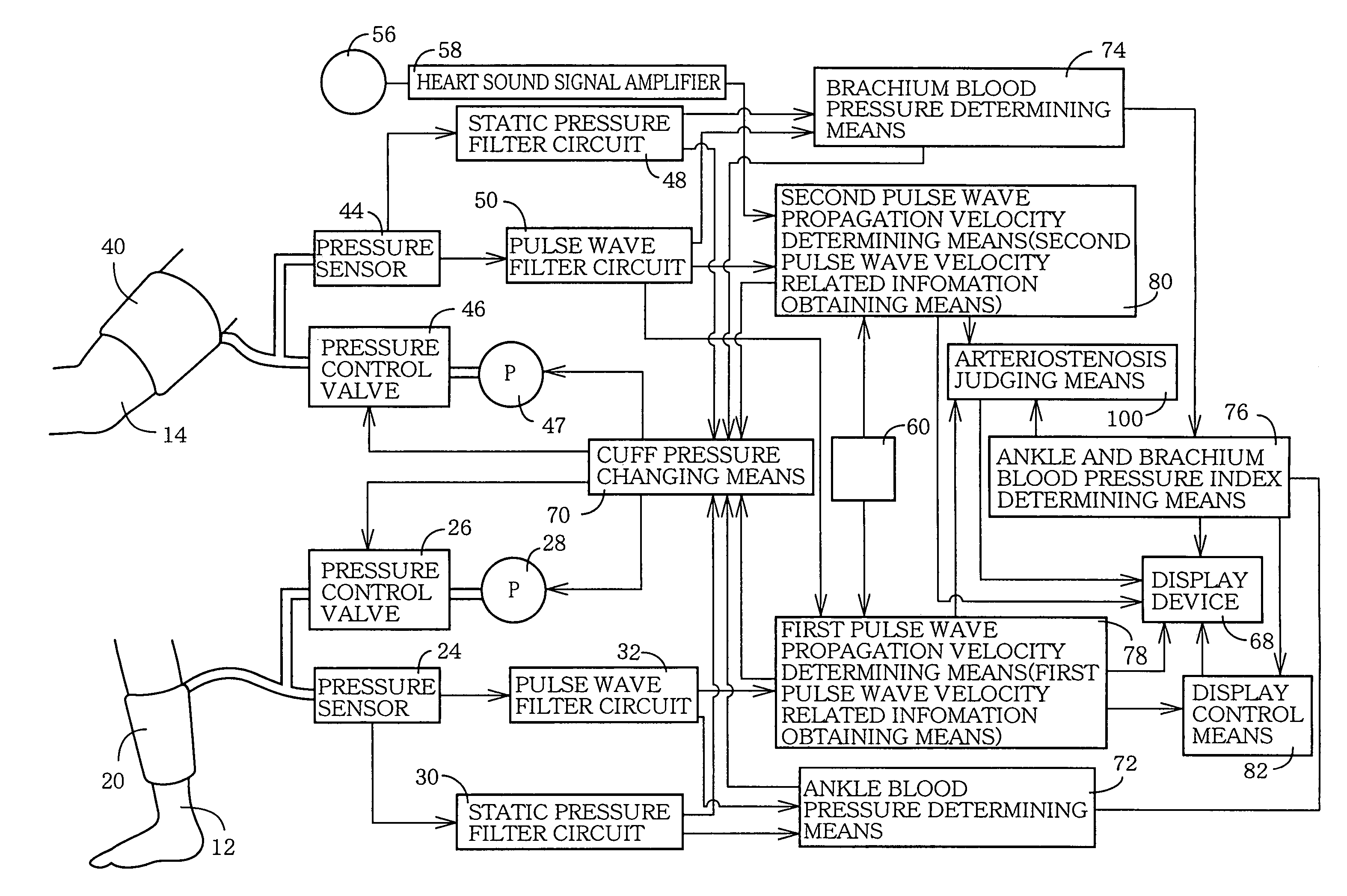
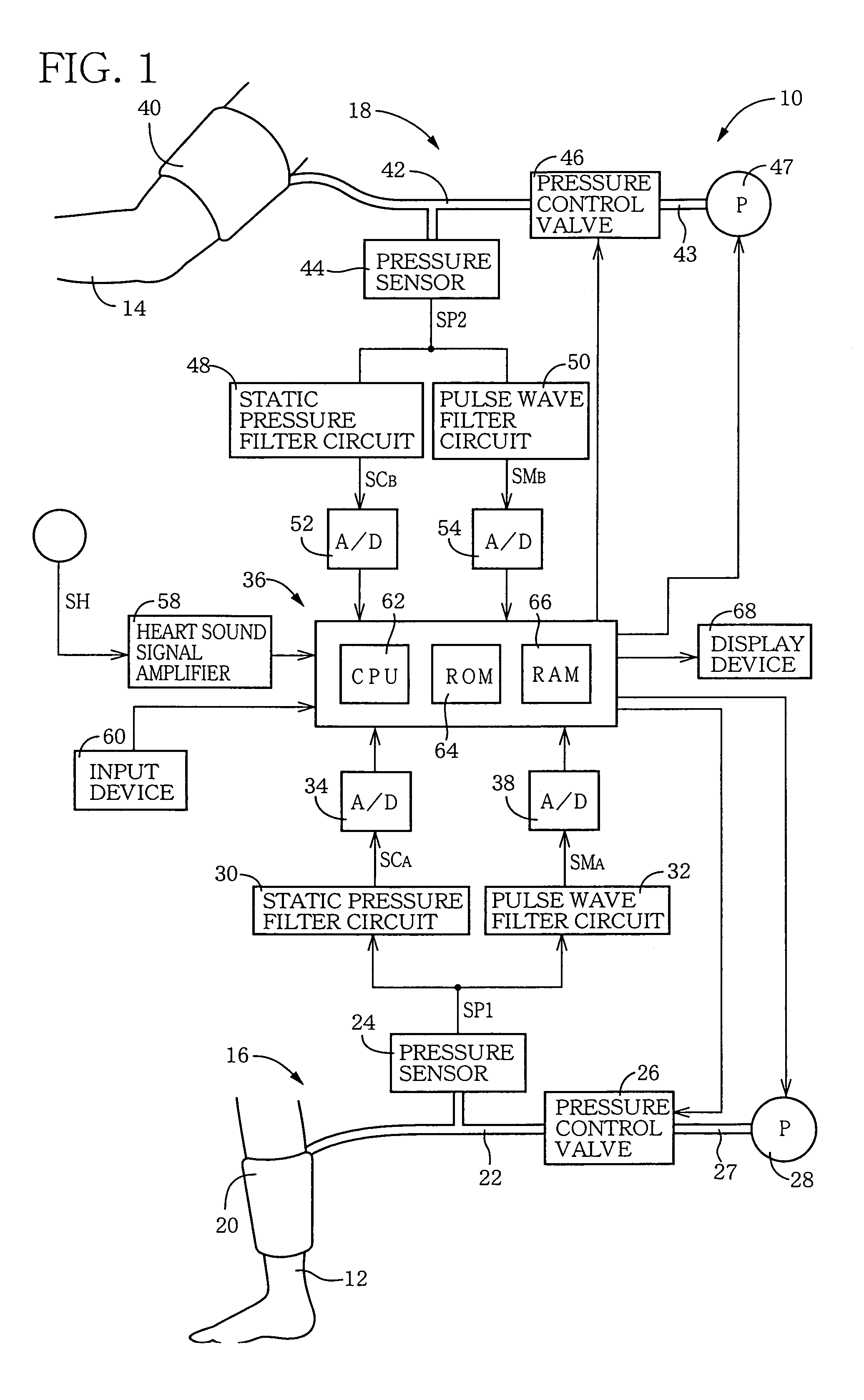
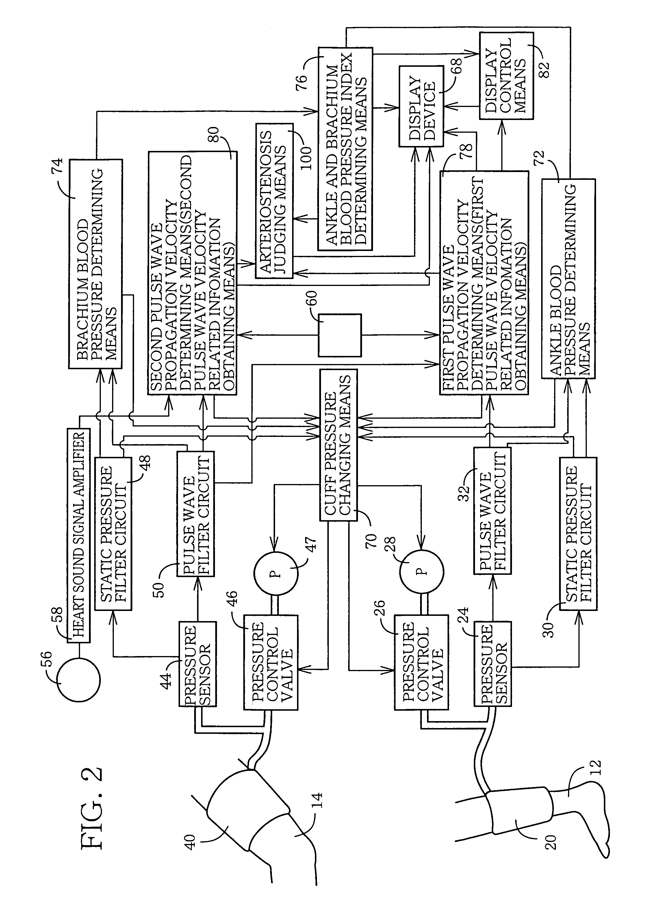
[0020]Hereinafter, there will be described a preferred embodiment of the present invention in detail by reference to the drawings. FIG. 1 is a diagrammatic view for explaining a construction of an arteriostenosis diagnosing apparatus 10. This diagnosing apparatus 10 performs measurements in a state in which a patient as a living subject takes a face-up position or a lateral position, so that a brachium 14 and an ankle 12 of the patient are substantially level with each other.

[0021]In FIG. 1, the arteriostenosis diagnosing apparatus 10 includes an ankle blood pressure measuring device 16 which measures a blood pressure of the ankle 12 and functions as an inferior limb blood pressure measuring device; and a brachium blood pressure measuring device 18 which measures a blood pressure of the brachium 14 and functions as a superior limb blood pressure measuring device.

[0022]The ankle blood pressure measuring device 16 includes an ankle cuff 20 which includes a belt-like cloth bag and a ru...


PUM


Abstract

An arteriostenosis diagnosing apparatus which measures an ankle blood pressure at an ankle 12 of a patient and a brachium blood pressure at a brachium 14, so that the measured ankle and brachium blood pressure values are used to calculate an ankle and brachium blood pressure index ABI, and additionally measures a first pulse wave propagation velocity PWV1 with respect to the ankle 12 as a first measuring point and the brachium 14 as a second measuring point, and a second pulse wave propagation velocity PWV2 with respect to the patient's heart and the brachium 14. The arteriostenosis diagnosing apparatus includes an arteriostenosis judging device 100 which judges, even if the index ABI may fall in a prescribed normal range or a prescribed alert range and the first velocity PWV1 falls in a prescribed normal range, that there is a possibility that an inferior limb including the ankle 12 at which the ankle blood pressure has been measured, may have arteriostenosis, if the second velocity PWV2 falls in a prescribed abnormal range.

Description

BACKGROUND OF THE INVENTION[0001]1. Field of the Invention[0002]The present invention relates to an arteriostenosis diagnosing apparatus which diagnoses arteriostenosis of a living subject based on an inferior and superior limb blood pressure index, and pulse wave velocity related information, obtained from the subject.[0003]2. Related Art Statement[0004]Inferior and superior limb blood pressure index is known as an index useful to diagnose arteriostenosis or arterial occlusion resulting from atherosclerosis. This index is expressed as the ratio of superior limb blood pressure to inferior limb blood pressure or the ratio of inferior limb blood pressure to superior limb blood pressure. Generally, systolic blood pressure values are measured to determine this index. In addition, generally, an ankle is used as the inferior limb and a brachium is used as the superior limb, i.e., ankle and brachium blood pressure index ABI is measured as the inferior and superior limb blood pressure index...

Claims


Application Information

Patent Timeline
Patent Type & Authority Patents(United States)
IPC IPC(8): A61B5/02A61B5/021A61B5/022A61B5/0245A61B5/0285
CPCA61B5/021A61B5/0285A61B5/02125
Inventor NARIMATSU, KIYOYUKI
Owner OMRON HEALTHCARE CO LTD
Why Eureka
Try Eureka