
Radiant floor heating and cooling system clip

a technology of heating and cooling system and radiant floor, which is applied in the direction of heater elements, lighting and heating apparatus, heating types, etc., can solve the problems of inability to use heating, control device and proper installation techniques that have not been perfected, and the use of tubing materials, etc., to achieve low manufacturing cost, low price of sale, and durable and reliable construction

Active Publication Date: 2005-11-29
MEYER ENTERPRISES
View PDF29 Cites 55 Cited by
  • Summary
  • Abstract
  • Description
  • Claims
  • Application Information

AI Technical Summary

Benefits of technology

[0020]Therefore, it is an object of the present invention to provide a new and improved radiant floor heating and cooling system clip which may be easily and efficiently manufactured and marketed. Likewise, the present invention works in cooperation with existing radiant floor heating and cooling system components and will not deteriorate.
[0026]An even further object of the present invention is to provide a new and improved radiant floor heating and cooling system clip that will not collapse, cut or otherwise restrict the tubing used to pass heating and cooling fluids.

Problems solved by technology

In the past, tubing materials, control devices and proper installation techniques had not been perfected and so radiant heating was not used.
In the prior art, such placement is routinely time consuming due to the inherit issue of holding a “bend” in the tube without restricting, crushing or otherwise damaging the tube while the concrete is poured and allowed to harden.
This method does not allow for quick use and frequently causes a poor installation when the tie is too tight thereby damaging the tube or otherwise restricting the passageway of the tube.
Furthermore, if the tie is not tight enough, it allows too much movement of the tube during the pouring of the concrete which in turn may damage or otherwise impede the passageway of the tubing.
Likewise, this method often leads to poor installation when the wire is too tight and thus restricting or damaging the passageway of the tubing or conversely being too lose wherein the tubing is allowed to move from its desired shape during the pouring and setting of the concrete.
Although there are numerous clips and fasteners, the prior art has failed to bridge the gap between industry needs and currently available products.

Method used


Image

  • Radiant floor heating and cooling system clip
  • Radiant floor heating and cooling system clip
  • Radiant floor heating and cooling system clip

Examples


Embodiment Construction

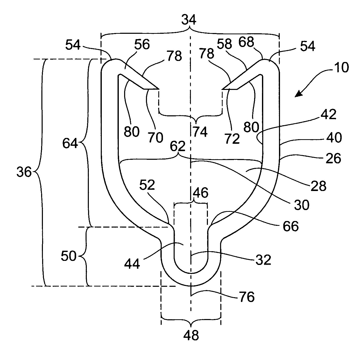
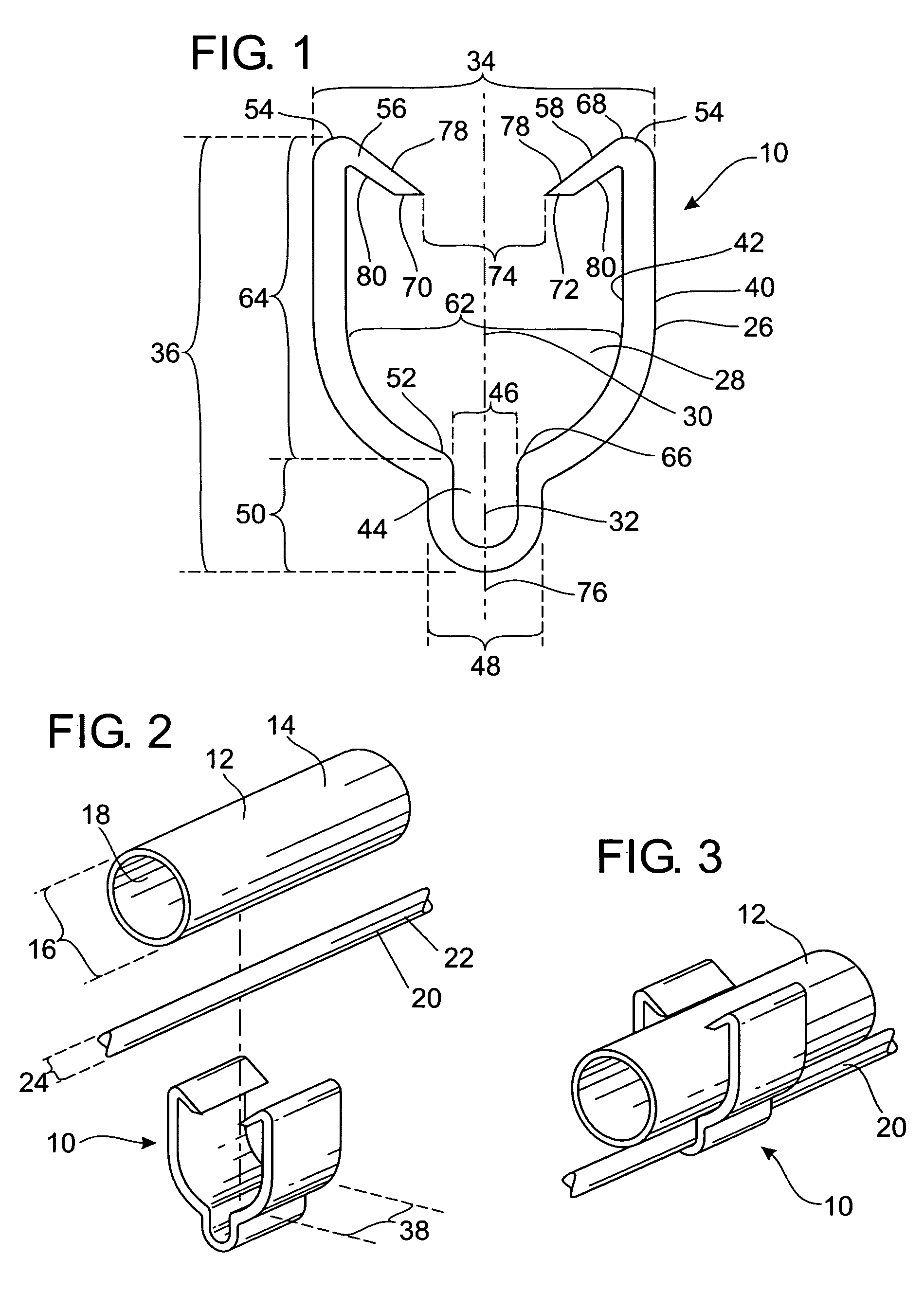
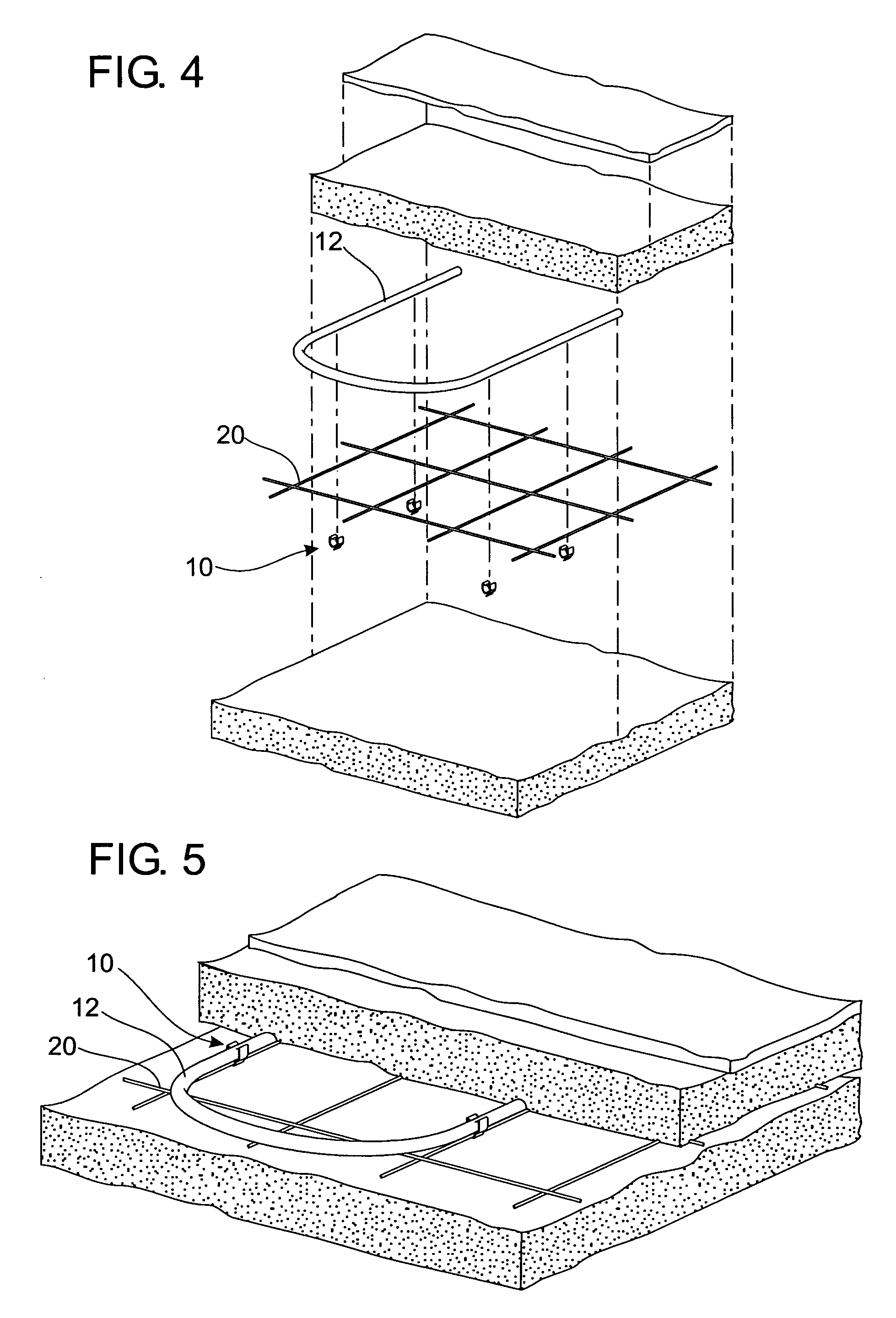
[0034]Referring to the drawings in detail and to FIGS. 1 and 2 in particular, reference character 10 generally designates a new and improved radiant floor heating and cooling system clip in accordance with the present invention. It is understood that the term “clip” should not be considered limiting and that the reference is to a fastener, connector and so forth that may hold at least two different items together in a secured fashion. In a preferred embodiment, invention 10 may generally be used for radiant floor heating and cooling systems which will be described in greater detail below.

[0035]It is contemplated that in a preferred construction, invention 10 is made from polyvinyl chloride polymer, also more commonly referred to as PVC. It is understood that other materials may be utilized or combination of materials such as other forms of plastic, composite materials, metals, wood, man made or natural rubber, and so forth. Furthermore, in a preferred construction, invention 10 is o...


PUM


Abstract

A radiant heating and cooling system clip for positioning a tube and construction support wire with one hand comprising an interior having a main channel for positioning a tube with a narrowing second channel within said main channel for positioning a wire.

Description

CROSS-REFERENCE TO RELATED APPLICATIONS[0001]Priority is claimed from provisional application U.S. Ser. No. 60 / 471,500 filed on May 19, 2003, and incorporated by reference herein.BACKGROUND OF THE INVENTION[0002]1. Field of the Invention[0003]In general, the present invention relates to an improved clip or fastener. More specifically, the present invention provides a cheap and efficient means to secure tubing commonly associated with radiant heating and cooling systems with wire mesh commonly associated with structural support with concrete in the construction of radiant floor heating and cooling systems.[0004]2. Description of the Prior Art[0005]Radiant floor heating (RFH) and radiant wall heating (RWH) are techniques of heating rooms in a dwelling or commercial building for human and creature comfort. It is believed by many that radiant heating is the ideal way to warm the human body. Europeans have revitalized a modern form of hydronic radiant floor heating in the last few decade...

Claims


Application Information

Patent Timeline
Patent Type & Authority Patents(United States)
IPC IPC(8): F24D3/14H05B3/06
CPCF24D3/141F24D3/144H05B3/06Y02B30/00
Inventor DAUGHTRY, SR., TIMOTHY DOUGLAS
Owner MEYER ENTERPRISES
Learn More