
Method of generating images to aid in the detection of manmade objects in cluttered underwater environments

a technology of underwater environment and image, applied in the field of underwater detection schemes, can solve the problems of high cost, time-consuming and tiring process, and the expected high-frequency noise of acoustical methods, and achieve the effect of simplifying the detection of manmade objects

Inactive Publication Date: 2005-11-29
THE UNITED STATES OF AMERICA AS REPRESENTED BY THE SECRETARY OF THE NAVY
View PDF7 Cites 33 Cited by
  • Summary
  • Abstract
  • Description
  • Claims
  • Application Information

AI Technical Summary

Benefits of technology

[0007]Still another object of the present invention is to provide a method of generating an image of manmade objects residing in an underwater environment having coral reefs.
[0008]Yet another object of the present invention is to provide a method of generating an image of an underwater environment where the image simplifies the detection of manmade objects by excluding clutter.
[0009]A still further object of the present invention is to provide a method of generating isolated images of manmade objects in cluttered underwater environments where the images of the manmade objects are isolated from images of naturally-occurring clutter.

Problems solved by technology

This is especially true in highly cluttered areas.
A coral reef is an area where acoustical methods are expected to generate many false alarms.
This is due to the massive amounts of “biological clutter” in the scene.
However, in a coral reef (or other highly cluttered environment) where the density of “mine-like contacts” is high, this process is very time consuming and tiring.

Method used


Image

  • Method of generating images to aid in the detection of manmade objects in cluttered underwater environments
  • Method of generating images to aid in the detection of manmade objects in cluttered underwater environments
  • Method of generating images to aid in the detection of manmade objects in cluttered underwater environments

Examples


Embodiment Construction

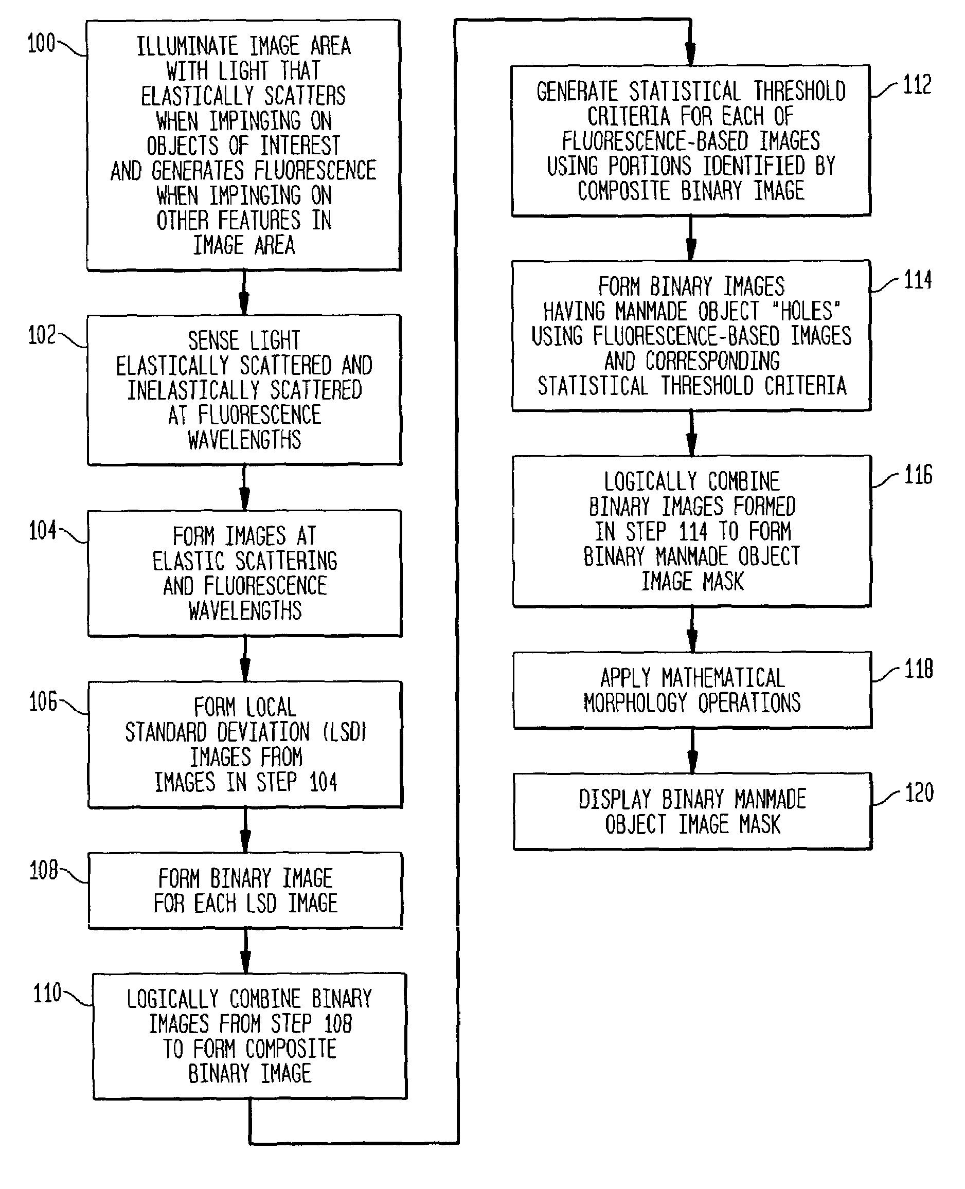
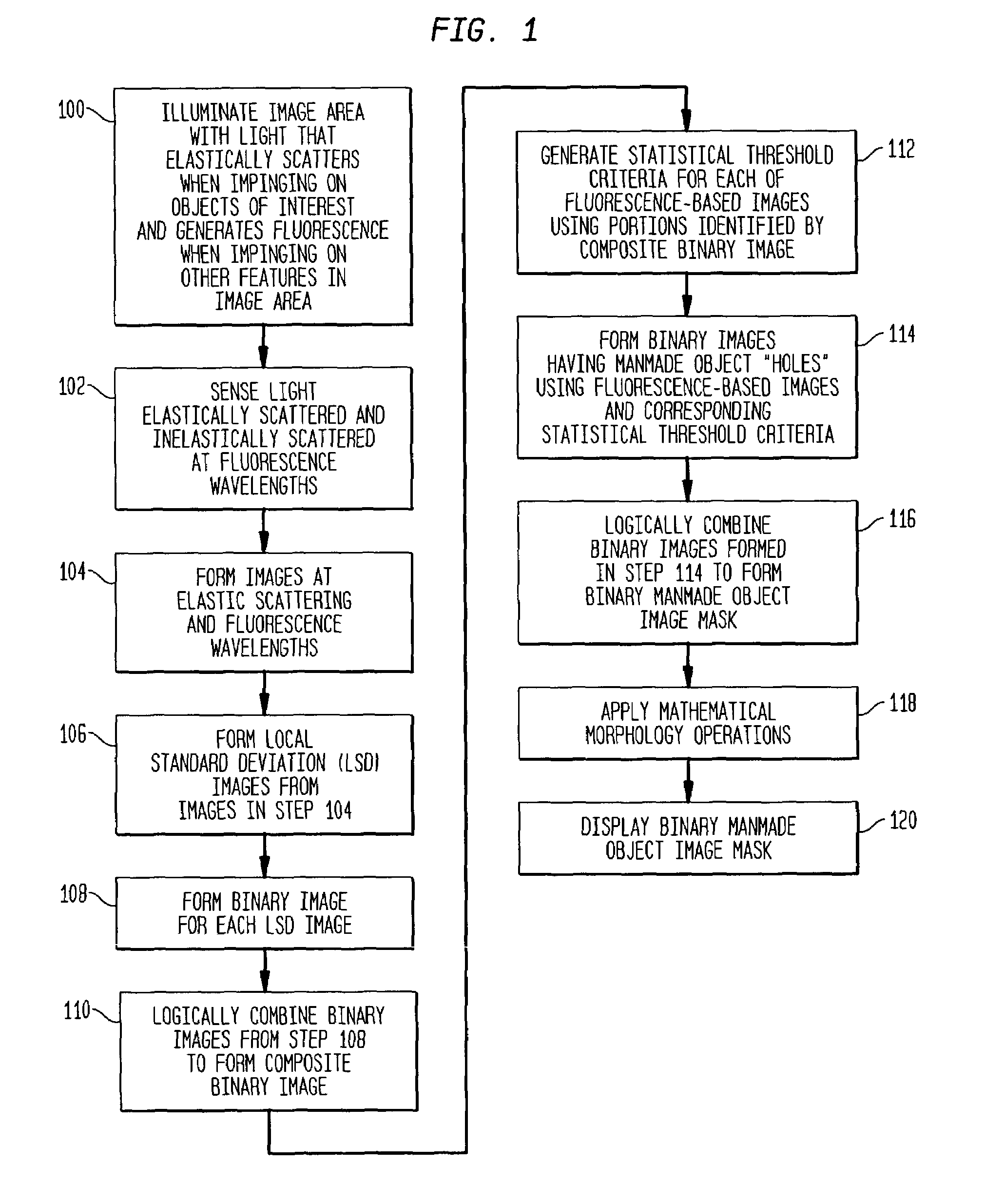
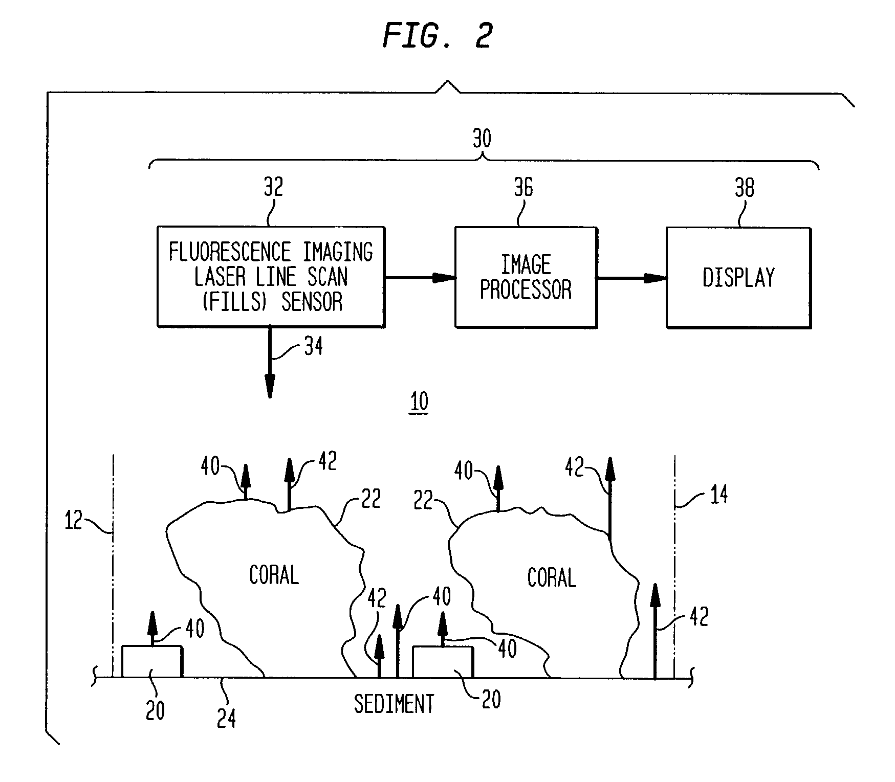
[0015]Referring now to the drawings, simultaneous reference will be made to FIGS. 1 and 2 where FIG. 1 depicts the method of generating an isolated image of manmade objects residing in an underwater environment in the form of a flow diagram and FIG. 2 is a block diagram of a system 30 that can be used to carry out the method outlined in FIG. 1. By way of illustrative example, the present invention will be explained for use in an underwater environment containing coral reefs. However, it is to be understood that the present invention can be used in any underwater environment and is particularly well suited for use in cluttered underwater environments.

[0016]An underwater area 10 to be examined is illustrated as the area between dashed lines 12 and 14 in FIG. 2. Within image area 10 are a number of features to include manmade objects 20, coral 22 and the sediment 24 that comprises the sea floor. The goal of the present invention is to form an image of area 10 that isolates manmade obje...


PUM


Abstract

An underwater image area is illuminated with light generating elastic scattering from manmade objects and naturally-occurring features, and fluorescence from naturally-occurring features. Local standard deviation (LSD) images are formed using the elastic scattered and fluorescent light. Elements of each LSD image are compared to threshold criteria to generate: i) first binary images having first image state portions indicating manmade objects and naturally-occurring features, and ii) second image state portions indicating background. The first binary images are logically combined generating a composite image mask. Statistical threshold criteria for each fluorescence-based image is generated using only portions identified by portions of the composite image mask indicating of background. Elements of each fluorescence-based image are compared to statistical threshold criteria to generate second binary images. At least two second binary images are logically combined to generate a binary manmade object image mask delineates between manmade objects and everything else.

Description

ORIGIN OF THE INVENTION[0001]The invention described herein was made in the performance of official duties by an employee of the Department of the Navy and may be manufactured, used, licensed by or for the Government for any governmental purpose without payment of any royalties thereon.FIELD OF THE INVENTION[0002]The invention relates generally to underwater detection schemes, and more particularly to a fluorescence imagery-based method of generating images that can be used to aid in the detection of manmade objects in cluttered underwater environments.BACKGROUND OF THE INVENTION[0003]Mine hunting is traditionally performed by a combination of acoustic methods (i.e., sonar) and optical methods. Traditionally, detection and classification of mine-like contacts are performed by acoustical methods. During such operations, “contacts” are classified as “mine-like” only if they are sufficiently similar to known signatures of mines. Many of the sonar contacts classified as “mine-like” will...

Claims


Application Information

Patent Timeline
Patent Type & Authority Patents(United States)
IPC IPC(8): G06K9/00G06K9/20G06K9/36H04N7/18
CPCG06K9/00637G06V20/176
Inventor STRAND, MICHAEL P.
Owner THE UNITED STATES OF AMERICA AS REPRESENTED BY THE SECRETARY OF THE NAVY
Learn More