Dynamically configuring resources for cycle translation in a computer system

a computer system and cycle translation technology, applied in the field of computer devices, can solve the problems of inability to write, test and debug a hal in time, and the cost of writing, testing and debugging a hal may be on the order of several millions of dollars, and it is impractical for an operating system vendor to write a new hal

Inactive Publication Date: 2005-11-29
MICROSOFT TECH LICENSING LLC
View PDF8 Cites 121 Cited by
  • Summary
  • Abstract
  • Description
  • Claims
  • Application Information

AI Technical Summary

Benefits of technology

[0004]Briefly, the present invention provides a method and system that removes the function of resource translation out of the HAL. This enables customized machines to be more readily developed, as instead of requiring an entire HAL to provide resource translation, the resource translator may be dynamically determined for each particular piece of hardware.

Problems solved by technology

It is thus an extremely complex piece of software code to develop.
Indeed, the contemporary cost to write, test and debug a HAL may be on the order of several millions of dollars.
It is impractical for an operating system vendor to write a new HAL for each new machine that is developed, and machine vendors thus need to fit new machines into one of the broad categories covered by one of the several HAL implementations currently available, or write their own HAL for a machine that is not covered.
However, because of the cost and complexity reasons, only a few, very large original equipment manufacturers have attempted to write a HAL to attempt to support a new class of machines, with mixed results.
As a result, most equipment manufacturers are limited to providing classes of computer systems that are capable of working with an already-existing HAL.

Method used


Image

  • Dynamically configuring resources for cycle translation in a computer system
  • Dynamically configuring resources for cycle translation in a computer system
  • Dynamically configuring resources for cycle translation in a computer system

Examples


Embodiment Construction

[0016]Copyright Notice

[0017]A portion of the disclosure of this patent document may contain material which is subject to copyright protection. The copyright owner has no objection to the facsimile reproduction by anyone of the patent document or the patent disclosure, as it appears in the Patent and Trademark Office patent file or records, but otherwise reserves all copyright rights whatsoever.

[0018]Exemplary Operating Environments

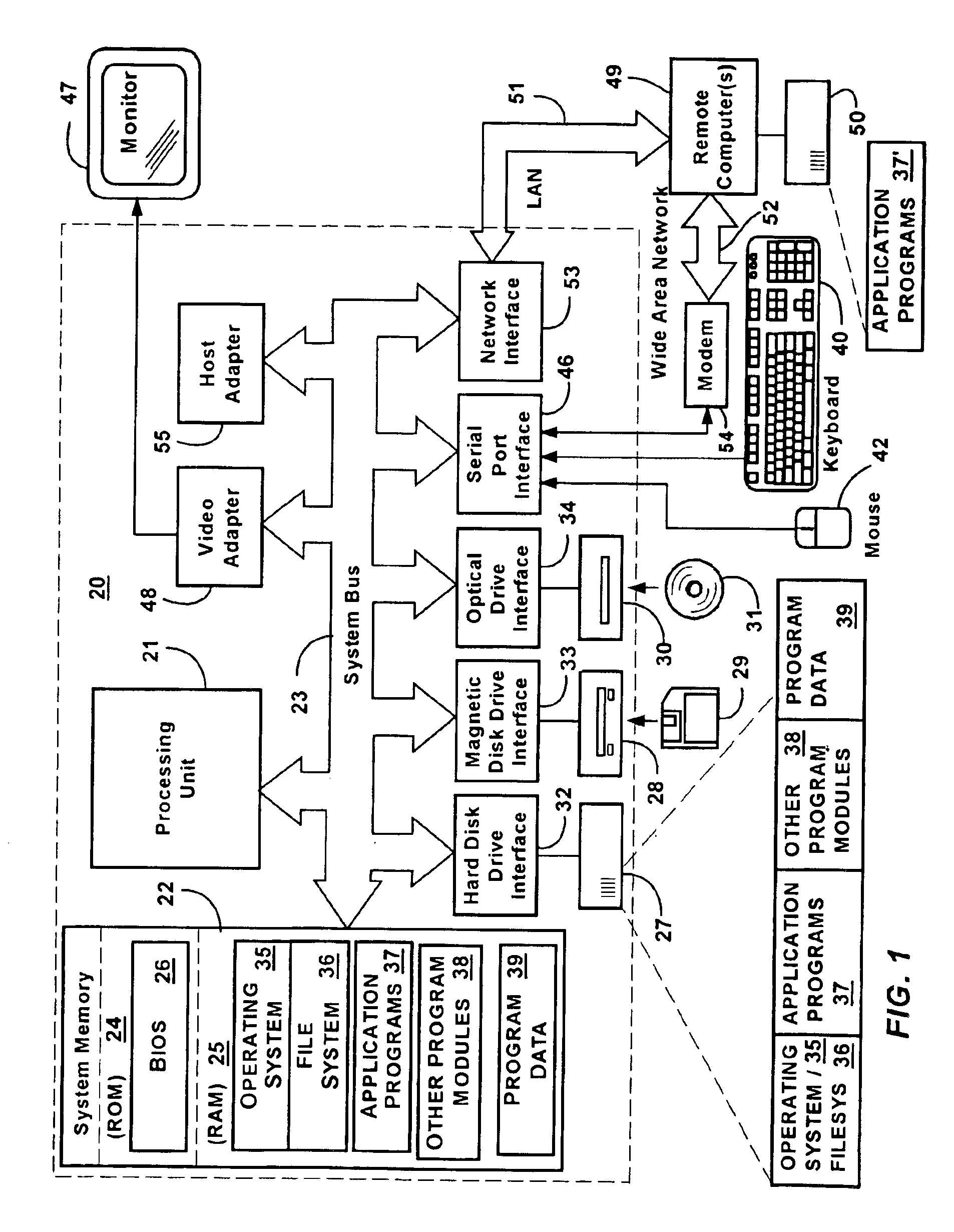
[0019]FIG. 1 and the following discussion are intended to provide a brief general description of a suitable computing environment in which the invention may be implemented. Although not required, the invention will be described in the general context of computer-executable instructions, such as program modules, being executed by a personal computer. Generally, program modules include routines, programs, objects, components, data structures and the like that perform particular tasks or implement particular abstract data types.

[0020]Moreover, those skilled i...


PUM


Abstract

A method and system that enables customized computer machines to be more readily developed by removing the function of resource translation out of the hardware abstraction layer (HAL). A machine manufacturer describes a machine in firmware, such as accordance with the Advanced Configuration and Power Interface (ACPI) specification, using ACPI machine language (AML). Operating system components such as a Plug and Play (PnP) manager in the kernel, in conjunction with an ACPI driver, interpret the description information and locate resources (bus bridges) for which translation is needed. For any arbitrary bus architecture or CPU to PCI bridge implementation that can be expressed, e.g., in ACPI firmware, the invention provides a translator external to the HAL. In one implementation, a PnP driver communicates with the ACPI driver and various drivers in driver stacks via I / O request packets (IRPs) to look for resource translators. The ACPI driver analyzes the machine description and returns a translator if found for such a resource. The resource is then configured to output cycles based on the translator.

Description

FIELD OF THE INVENTION[0001]The present invention relates generally to computer devices, and more particularly to computer software for facilitating the development of customized computer hardware.BACKGROUND OF THE INVENTION[0002]The Hardware Abstraction Layer, or HAL, is a complex part at a low layer of the Windows® 2000 (or Windows NT®) operating system that abstracts hardware differences among various system architectures from higher layers of software. The HAL enables higher-level operating system components and drivers to communicate with the system hardware without modification, i.e., the HAL enables a single driver to support the same hardware device on multiple platforms. For example, one of the many tasks performed by the HAL is resource translation, wherein on certain (e.g., non-x86) processors that can only read and write in memory cycles, certain CPU-relative memory cycles are translated to bus-relative cycles (I / O or other memory address), and vice-versa, so that device...

Claims


Application Information

Patent Timeline
Patent Type & Authority Patents(United States)
IPC IPC(8): G06F1/00G06F17/50
CPCG06F9/4411
Inventor OSHINS, JACOBPLANTE, STEPHANE G.THORNTON, ANDREW J.
Owner MICROSOFT TECH LICENSING LLC
Why Eureka
Try Eureka