

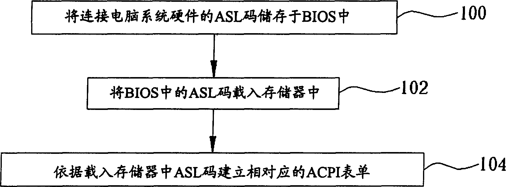
Method for dynamically establishing high-level configuration and power source interface architecture
A power management and configuration technology, applied in the direction of response error generation, redundant code error detection, hardware monitoring, etc., can solve problems such as cost of firmware program and trouble for firmware designers.
- Summary
- Abstract
- Description
- Claims
- Application Information
AI Technical Summary
Problems solved by technology
Method used
Image

Examples
Embodiment Construction
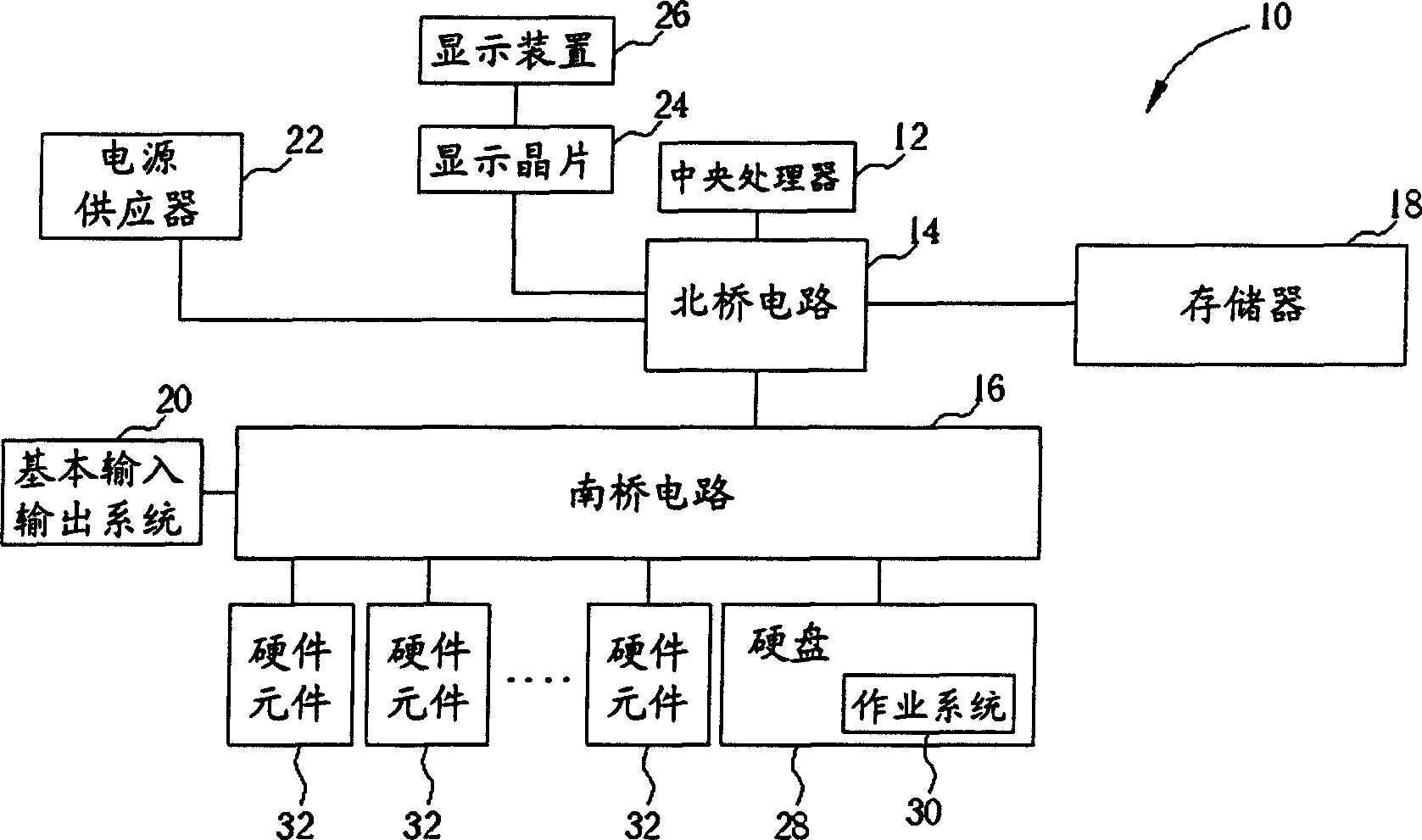
[0015] See figure 2 , figure 2 It is a functional block diagram of the computer system 10 of the present invention. The computer system 10 includes a central processing unit 12, a north bridge circuit 14, a south bridge circuit 16, a memory 18, a basic input output system 20, a power supply 22, a display chip 24, and is electrically connected to the north bridge circuit 14. A display device 26 is connected to the display chip 24 and a hard disk 28 is electrically connected to the south bridge circuit 16. It stores an operating system 30 and a plurality of hardware components 32 that are electrically connected to the south bridge circuit 16.
[0016] The central processing unit 12 is used to control the overall operation of the computer system 10, and the north bridge circuit 14 is used to control the data transfer between the central processing unit 12, the memory 18 and the display chip 24 with display function. The received image data is converted into an image signal to displ...
PUM
 Abstract
Description
Claims
Application Information