Magnetic detent for rotatable knob

a magnetic detent and rotatable technology, applied in mechanical control devices, wing knobs, instruments, etc., can solve the problems of changing the feel and sound of the detent as the plate, the detent can be significantly reduced to the point of being almost undetectable, and the tactile and audible feedback can be significantly reduced to the point of being nearly undetectabl

Inactive Publication Date: 2005-12-06
TERUMO CARDIOVASCULAR SYST CORP
View PDF18 Cites 81 Cited by
  • Summary
  • Abstract
  • Description
  • Claims
  • Application Information

AI Technical Summary

Benefits of technology

[0013]A further preferred embodiment of the present invention is directed to a knob assembly comprising a rotatable knob having an under surface and a top surface for gripping by a user, a notched plate rotatable with the rotatable knob and arranged proximate to the under surface of the rotatable knob, and a magnetic detent assembly disposed substantially stationary proximate to the notched plate. Rotation of the rotatable knob and the notched plate over the magnetic detent assembly thus provides a user with an audible indicator of rotation.

Problems solved by technology

However, both the tactile and audible feedback can be significantly reduced to the point of being nearly undetectable if there is significant resistance to the movement of the plate or disk.
For instance, when there is a significant resistance to the rotation of the adjustment knob, such as caused by increased compression of the flexible tube, for instance, the feel and sound of a spring loaded detent may be almost undetectable.
In addition, the metal-to-metal contact between the plate and the spring loaded ball or plunger tends to create wear which in turn may affect the precise positioning required by the spring loaded ball within the slots or shallow holes of the plate.
More particularly, the corners of the notches or holes in a spring loaded detent plate or disk will tend to become rounded, changing the feel and sound of the detent as the plate wears under contact.

Method used


Image

  • Magnetic detent for rotatable knob
  • Magnetic detent for rotatable knob
  • Magnetic detent for rotatable knob

Examples


Embodiment Construction

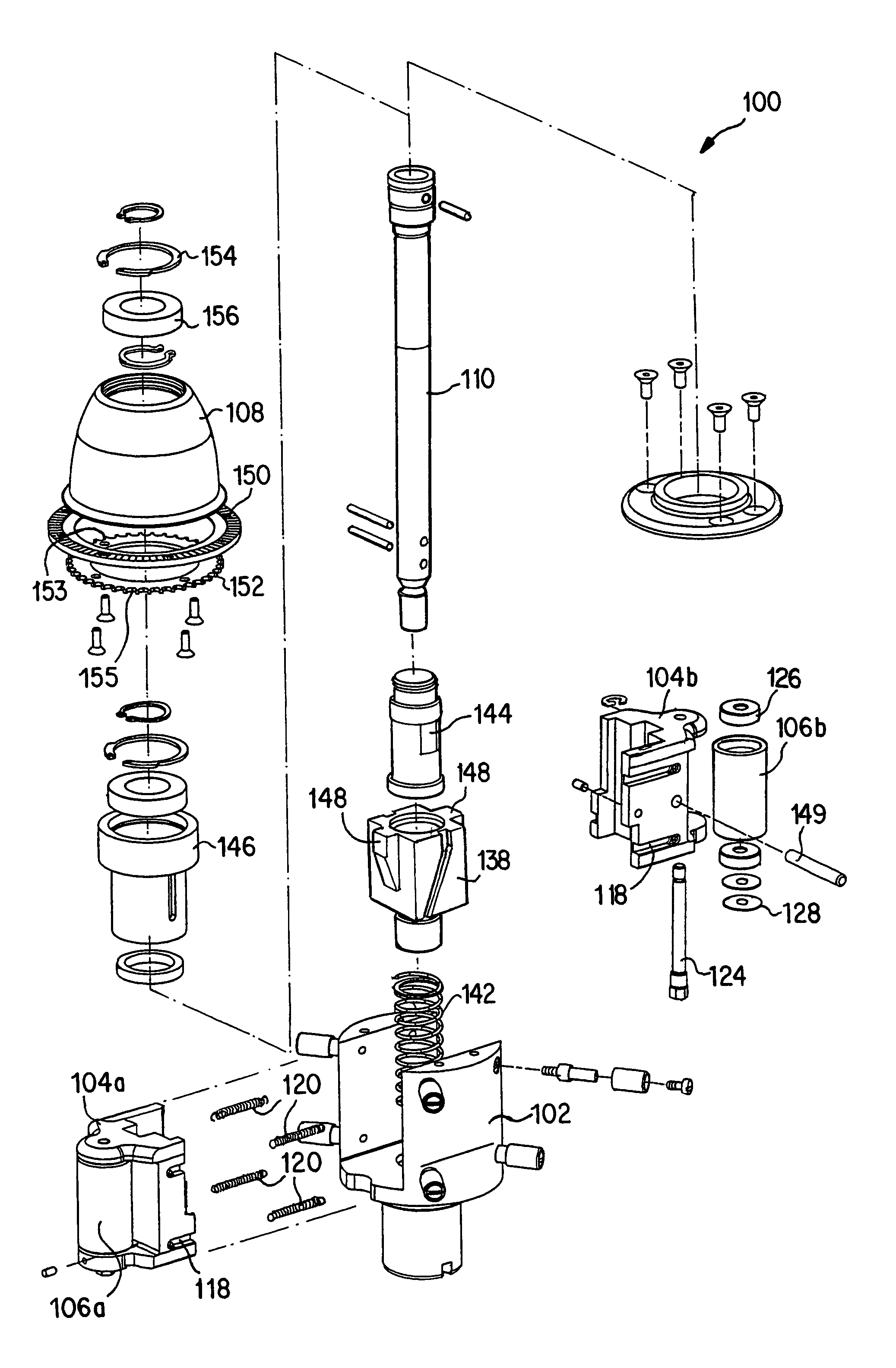
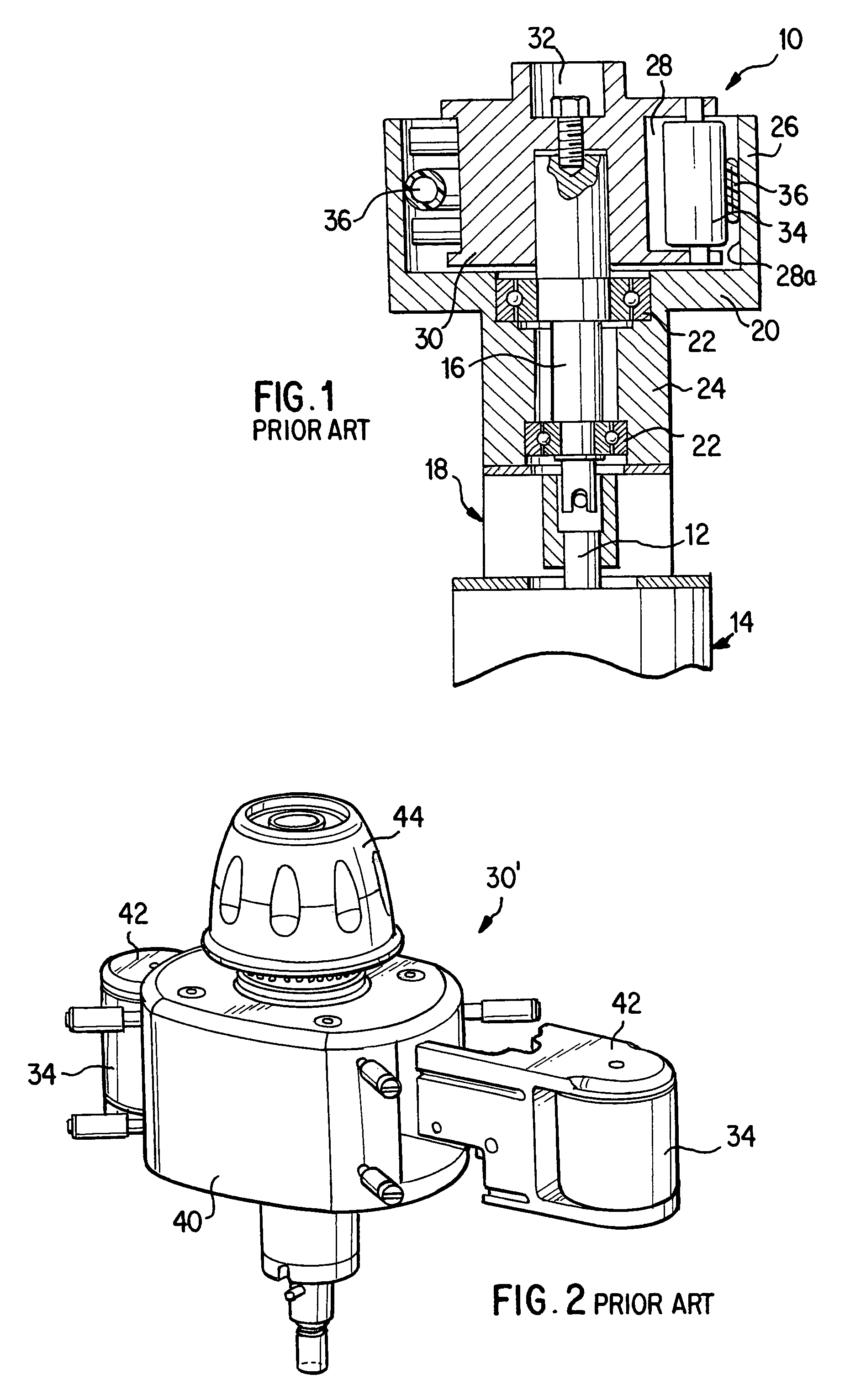
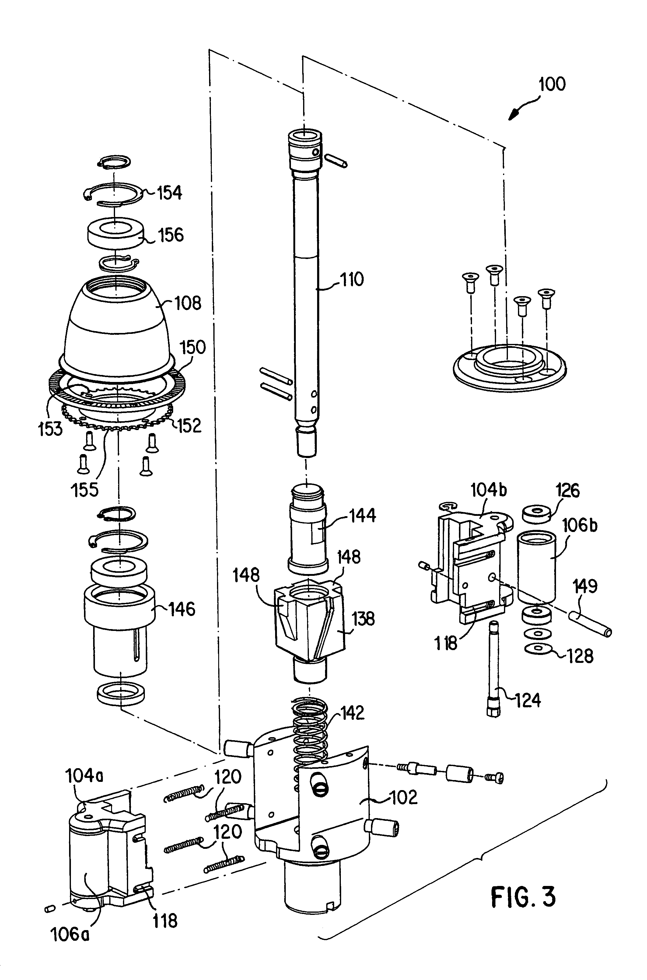
[0025]A peristaltic pump rotor assembly according to the present invention is shown generally by reference numeral 100 in the exploded view of FIG. 3. Rotor assembly 100 includes a pump or rotor hub 102, at least one and preferably two opposing roller slides 104a, 104b, a roller 106a, 106b disposed within each roller slide, respectively, and an adjustment knob 108 for adjusting the occlusion of the flexible tube within the pump. The rotor assembly 100 is rotatably supported within a stator similar to that shown in FIG. 1 and as known in the art, and the inner circumferential surface of the stator forms the raceway for the rollers 106a, 106b of the present invention. A main shaft 110 extending through the rotor assembly 100 rotates according to the rotation of a drive shaft, which is rotated by a conventional drive mechanism, as shown in FIG. 1, for example.

[0026]Each of the roller slides 104a, 104b includes a plurality of recesses or channels 118 for receiving an extension spring 12...


PUM


Abstract

A roller pump including a stator and a rotor assembly disposed within the stator. The rotor assembly includes a rotor hub, a first roller slide and a second roller slide slidingly disposed within the rotor hub. Each of the roller slides rotatably supports a roller. An occlusion adjustment knob for adjusting a radial position of the first and second roller slides and a magnetic detent assembly for providing an audible indicator as the occlusion adjustment knob is rotated.

Description

[0001]This application is a divisional of application Ser. No. 10 / 077,769, filed on Feb. 20, 2002, now U.S. Pat. No. 6,607,363.TECHNICAL FIELD[0002]The present invention is directed to a detent assembly for a rotatable knob, and more particularly, to a magnetic detent assembly for providing audible feedback during the rotation of an occlusion adjustment knob on a peristaltic pump.BACKGROUND OF THE INVENTION[0003]Peristaltic pumps are commonly utilized in medical applications. For instance, such pumps are often employed during cardiovascular surgery to facilitate circulation of blood between a patient and a heart-lung machine. Other common medical uses are the transfer of blood between a patient and a kidney dialyzer, and intravenous feeding of IV solutions. Generally, peristaltic pumps are simply structured, generate a constant flow, and employ disposable tubes as a member for fluid transfer.[0004]Peristaltic pumps are relatively simple in construction and typically include a housin...

Claims


Application Information

Patent Timeline
Patent Type & Authority Patents(United States)
IPC IPC(8): F04B43/12
CPCF04B43/1253F04B43/1276Y10T16/506H01H2003/506A61M60/109A61M60/279A61M60/37A61M60/38A61M60/441
Inventor DOMROESE, MICHAEL K.
Owner TERUMO CARDIOVASCULAR SYST CORP
Why Eureka
Try Eureka