Body weight gravity apparatus

a gravity apparatus and body weight technology, applied in the field of exercise machines, can solve the problems of affecting the efficiency affecting the performance of the body weight,

Inactive Publication Date: 2005-12-06
MATTHEWS PRODN
View PDF13 Cites 67 Cited by
  • Summary
  • Abstract
  • Description
  • Claims
  • Application Information

AI Technical Summary

Benefits of technology

[0017]two cushioning members having one end pivoted to each side of said lower rocking bar member and another end pivoted to each corresponding side of said connection bar for enabling said lower rocking bar member to return to a stationary position at a moderate pace.

Problems solved by technology

Such a conventional exercise machine as described above is defective in that its weights are costly and that it is expensive and inconvenient to transport.
Plastic rod systems lack the proper resistance and wear out to rapidly.

Method used


Image

  • Body weight gravity apparatus
  • Body weight gravity apparatus
  • Body weight gravity apparatus

Examples


Embodiment Construction

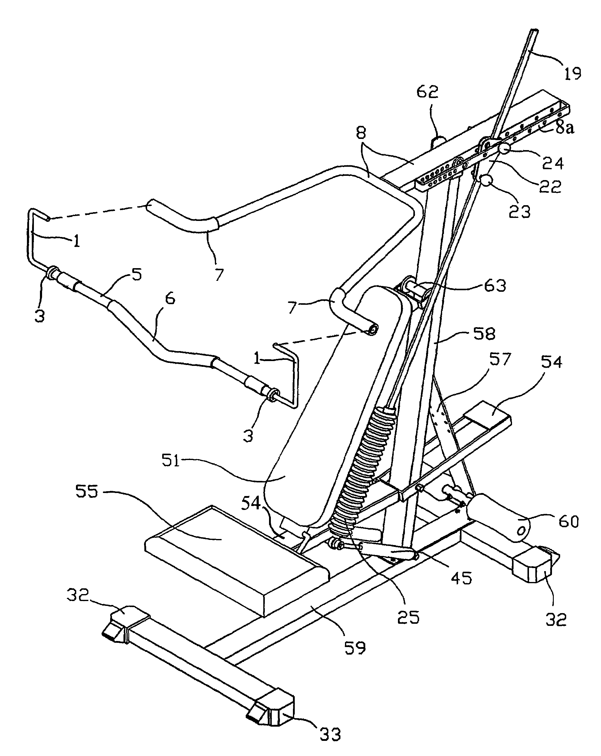
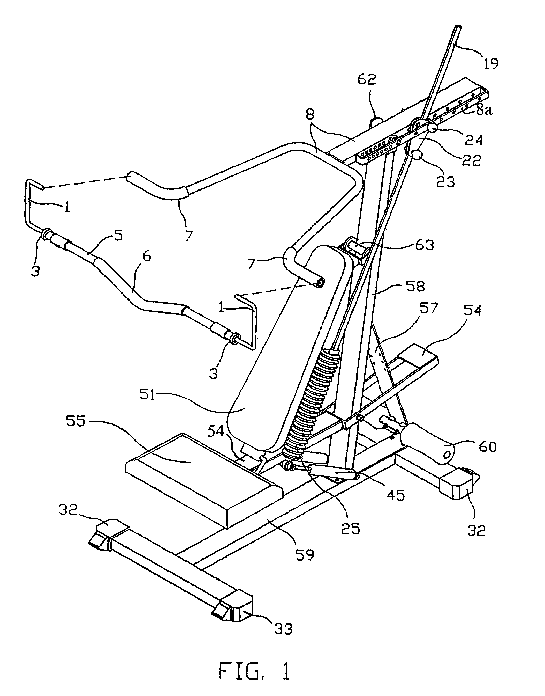
[0033]As shown in FIG. 1, the exercise machine of the present invention is made up of the component parts described hereinafter.

[0034]A horizontal base 59 is composed of a main tube and two cross tubes fastened vertically and respectively to both ends of the main tube of horizontal base 59 and have a set of end caps with rollers 32 and 33 (on both sides). The horizontal base 59 is placed horizontally on a flat surface.

[0035]A vertical bar member 58 is fastened obliquely to the horizontal base 59. The upper rocking bar member 8, including a parallel elongate bar 8a, is provided with a predetermined number of through holes located on the side and is pivoted by means of a pivot assembly 62 that comprises of a flange and bushing, or a bearing and sleeve assembly that allows the upper rocking bar member 8 to pivot.

[0036]A lower rocking rod member 54 comprises two parallel beams, one support tube fastened to the two parallel beams. The lower rocking bar member 54 is arranged at both sides...


PUM


Abstract

An exercise machine making use of the body weight of an exerciser as a load weight thereof comprises a horizontal base, a vertical bar member, an upper rocking bar member, a lower rocking bar member, a connection bar, a seat pad, a back pad, a handle, a pivoting cross member (V bar) and cushioning members. Unlike a conventional exercise machine, the exercise machine is composed of no weights. The vertical tube bar member is affixed to the base. The position of the upper rocking bar member can be adjusted by adjusting the pivoting position of the connection bar via the shuttle and two key pins. The exerciser can use the machine by sifting, kneeling, or standing on the seat pad of the machine for doing the muscle-building exercise.

Description

[0001]This application claims the benefit of Provisional Application No. 60 / 432,960, filed Dec. 12, 2002.FIELD OF THE INVENTION[0002]The present invention relates generally to an exercise machine, and more particularly to an exercise machine which makes use of the body weight of an exerciser as a load weight or the resistance provided by the machine to the exerciser.BACKGROUND OF THE INVENTION[0003]The conventional exercise machine is generally provided with various weights, which are lifted by means of steel cables and pulleys or fixed plastic rods that are bent by means of various cable and pulleys for the purpose of building the body of a person using the exercise machine. Such a conventional exercise machine as described above is defective in that its weights are costly and that it is expensive and inconvenient to transport. Plastic rod systems lack the proper resistance and wear out to rapidly.SUMMARY OF THE INVENTION[0004]It is therefore the primary objective of the present in...

Claims


Application Information

Patent Timeline
Patent Type & Authority Patents(United States)
IPC IPC(8): A61H1/02A63B21/068A63B21/078
CPCA61H1/0274A63B21/00072A63B21/068A63B21/078A63B21/1492A63B21/4047
Inventor HYDER, MATTHEW BRIAN
Owner MATTHEWS PRODN
Why Eureka
Try Eureka