Control of a switched reluctance drive

a technology of reluctance drive and control device, which is applied in the direction of synchronous motor starters, ac motor stoppers, electrical equipment, etc., can solve the problems of inability to control the output of the controller, small differences in parameter values that can produce undesirably large output variations, and inability to store controller spa

Inactive Publication Date: 2005-12-06
SWITCHED RELUCTANCE DRIVES
View PDF7 Cites 40 Cited by
  • Summary
  • Abstract
  • Description
  • Claims
  • Application Information

AI Technical Summary

Benefits of technology

[0027]According to a further aspect of the invention there is provided a control device for use in controlling the operation of a switched reluctance machine comprising a rotor having a plurality of poles, a stator having a plurality of poles and at least one phase winding, the control device comprising an input for receiving an angular position signal from position sensing means, said angular position signal being indicative of the angular position of the rotor with respect to the stator, an input for receiving a phase current signal indicative of the current in a phase winding, an output to output a control signal to a switching arrangement, and a processor arranged to monitor the signals received at the inputs and to generate the control signal, wherein the processor is arranged to generate a first control signal when the angular position signal indicates that the rotor is at a first pre-determined position, which first signal causes a voltage to be applied to the phase winding, and generate a second control signal when the phase current signal indicates that current in the phase winding is at a first pre-determined level, which second signal causes the phase winding to freewheel, thereby controlling the standing current in the phase winding.

Problems solved by technology

There is a particular difficulty in choosing values at the transition points between chopping and single-pulse modes, and between single-pulse and continuous current modes, where a smooth transition is desired regardless of the torque level demanded.
It is a feature of the continuous current mode that the sensitivity to angle parameters (particularly to the total conduction angle θc, which is the angular difference between θon and θoff) is much higher than in single-pulse mode, so small differences in parameter value can produce undesirably large variations in output.
While this is generally not a serious difficulty for switched reluctance systems in the chopping mode (since the current controller is generally capable of coping with the changing current gradients), it becomes a problem in single-pulse and continuous current modes, where the torque is strongly dependent on the supply voltage.
Known attempts to solve this problem include the storing of a complete set of control parameters for a range of supply voltages (i.e. introducing a further parameter, supply voltage, into the set), but this often creates unacceptable demands on storage space in the controller.
In the continuous current mode, however, these methods are seldom satisfactory.
The developed torque then immediately falls, leading to a drop in speed.
This sequence produces significant disturbance in the torque output, which can lead to the build up of oscillations and / or other instability.
Even if reliable thermal feedback from the winding were available at a reasonable cost, providing control parameters which compensated for temperature would place an unacceptable burden on storage in the controller.

Method used


Image

  • Control of a switched reluctance drive
  • Control of a switched reluctance drive
  • Control of a switched reluctance drive

Examples


Embodiment Construction

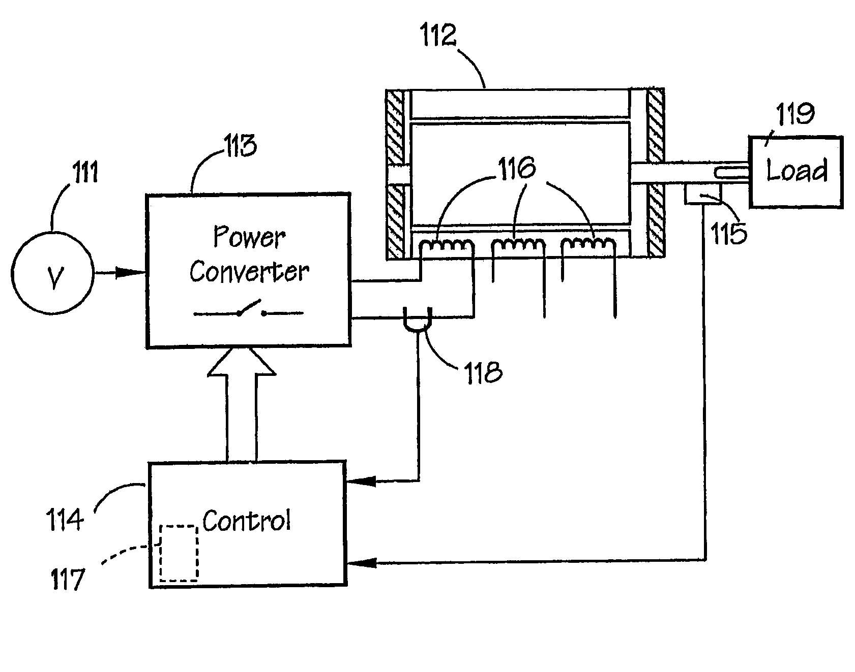
[0041]The phase inductance cycle of a switched reluctance machine is the period of the variation of inductance for the, or each, phase; for example the period between maxima when the rotor poles and the relevant respective stator poles are fully aligned. The illustrative embodiments to be described use a 3-phase switched reluctance drive, but any number of phases could be used, with the machine in either motoring or generating mode.

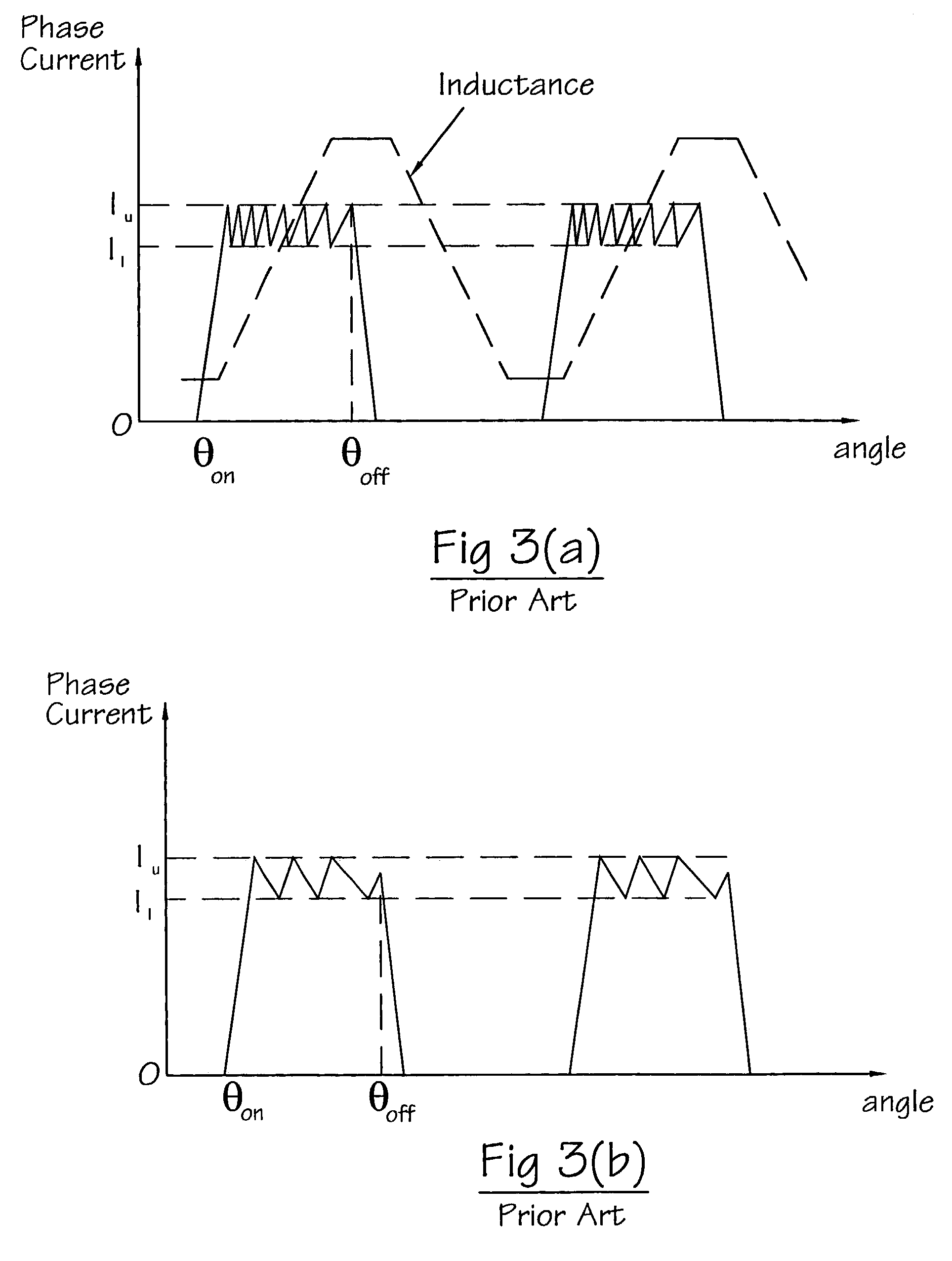
[0042]The method of control according to aspects of the invention uses a combination of switch-on angle, switch-off angle and current level to trigger an optional period of freewheeling which controls the standing current, Is, in the phase. Unlike previous methods of control in the continuous current mode, this method allows smooth control of the standing value of current with no abrupt dropping out of continuous current.

[0043]FIG. 7 shows a set of control parameters chosen according to embodiments of the invention. In operation, the phase is switched on ...


PUM


Abstract

A switched reluctance drive, operating either as a motor or a generator, is controlled in a stable manner in the continuous current mode in the presence of supply voltage or electrical load variation. The use of a current control parameter Ix in addition to the conventional on- and off-angles θon, θoff gives the ability to operate smoothly in the continuous current mode and to transition smoothly between operating modes. Once the phase current reaches a pre-determined level Ix, the phase winding may be placed in a freewheel state, thereby controlling the standing current in the phase winding and / or the output voltage.

Description

CROSS-REFERENCE TO RELATED APPLICATION[0001]The subject matter of this application is related to the subject matter of British Patent Application Nos. 0216990.2 and 0229841.2, filed Jul. 22, 2002 and Dec. 20, 2002 respectively, priority to both of which is claimed under 35 U.S.C. § 119 and both of which are incorporated herein by reference.BACKGROUND OF THE INVENTION[0002]1. Field of the Invention[0003]This invention relates to the control of reluctance machines, particularly of switched reluctance machines.[0004]2. Description of Related Art[0005]The control and operation of switched reluctance machines generally are described in the paper “The Characteristics, Design and Applications of Switched Reluctance Motors and Drives” by J. M. Stephenson and R. J. Blake delivered at the PCIM'93 Conference and Exhibition held in Nurnberg, Germany, 21–24 Jun. 1993 and incorporated herein by reference. In that paper “chopping” and “single-pulse” modes of energization of switched reluctance mac...

Claims


Application Information

Patent Timeline
Patent Type & Authority Patents(United States)
IPC IPC(8): H02P25/08
CPCH02P25/082H02P25/0925H02P25/08
Inventor JORDISON, IANPIRON, MARIELLE GHISLAINE ALBERTEMAYES, PETER RICHARDMURRAY, PETERTURNER, MICHAEL JAMESMCCLELLAND, MICHAEL LEO
Owner SWITCHED RELUCTANCE DRIVES
Why Eureka
Try Eureka