
Video signal processing device and its method

a video signal and processing device technology, applied in the field of video signal processing devices, can solve the problems of loss of chromatic tone of image, chromatic color fade, and drop of saturation of pixel, so as to prevent loss of color tone in image, reduce chromatic color fade of pixels, and reduce the effect of chromatic color fad

Inactive Publication Date: 2005-12-06
SONY CORP
View PDF14 Cites 21 Cited by
  • Summary
  • Abstract
  • Description
  • Claims
  • Application Information

AI Technical Summary

Benefits of technology

[0018]The present invention has been done considering the above points and is proposing a video signal processing device and its method capable of improving the quality of picture.
[0020]As a result, red signal, green signal and blue signal can be compression processed with tremendously reduced color fading of pixels, and the loss of chromatic tone in the image can be prevented.
[0022]As a result, red signal, green signal and blue signal can be compression processed with tremendously reduced chromatic color fading of pixels and thus, the loss of color tone in the image can be prevented.

Problems solved by technology

However, at the time when the gray level of pixel is dark, the part of red level, green level or blue level exceeding the luminance level is comparatively large, and if the upper limit of the red level, green level or blue level is controlled by the clip level according to the saturation knee processing, the saturation of this pixel drops extremely and chromatic color fades.
And thus, this caused the problem in losing chromatic tone of the image and worsening the quality of picture.

Method used


Image

  • Video signal processing device and its method
  • Video signal processing device and its method
  • Video signal processing device and its method

Examples


Embodiment Construction

[0029]The present invention will be described in detail with reference to the accompanying drawings.

(1) Principle of Knee Processing according to the Present Invention

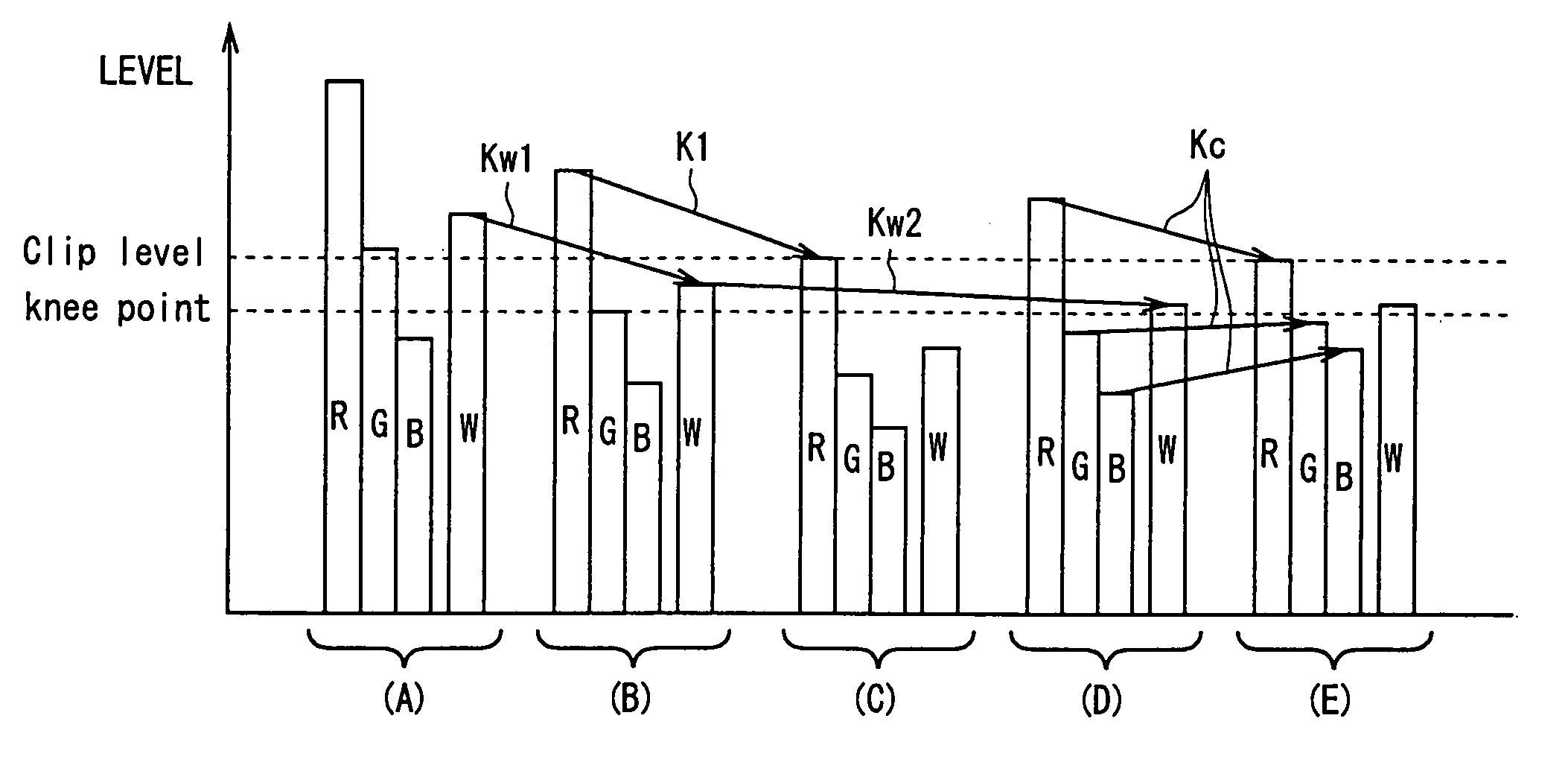
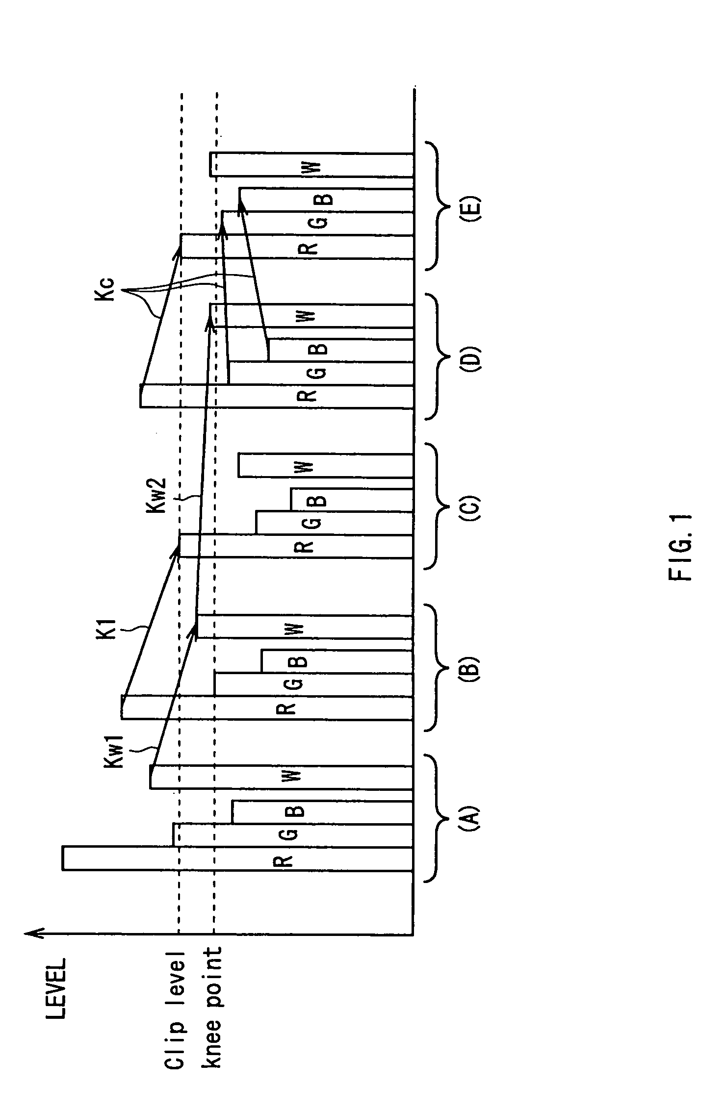
[0030]As shown in FIGS. 1(A)˜(E), according to the knee processing, firstly, the red signal, green signal and blue signal are multiplied by the first brightness transfer gain Kw1 respectively in the same manner as the luminance knee processing in the conventional knee processing, and the red level, green level and blue level will be reduced with the luminance level (FIG. 1(A)).

[0031]Then, in the case where either one of red level, green level and blue level exceeds the clip level even though the luminance knee processing is conducted, the temporary brightness transfer gain necessary for decreasing the red level, green level or blue level having the highest level at this moment (hereinafter referred to the first temporary brightness transfer gain) K1 will be obtained (FIG. 1(C)).

[0032]Then, in the case where the saturat...


PUM


Abstract

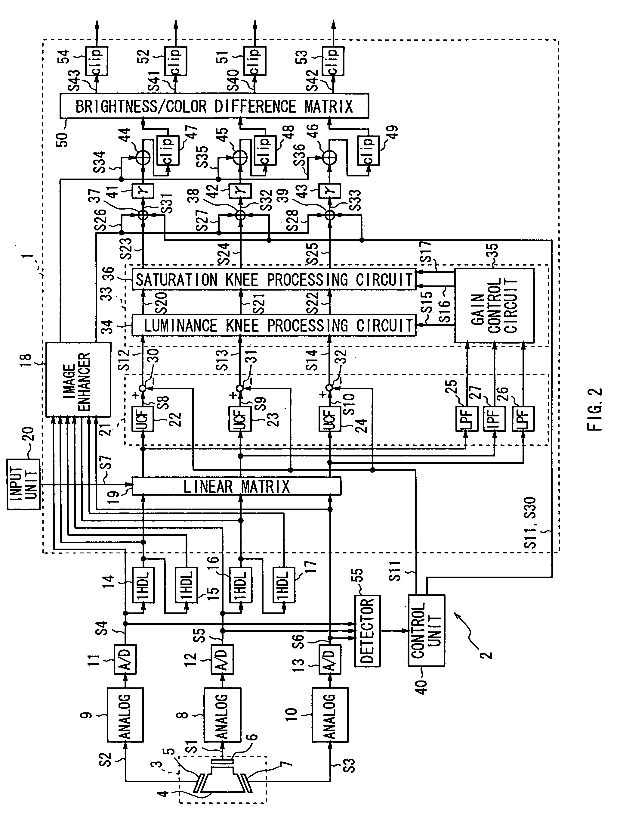
The object of the present invention is to improve the quality of picture in the image. According to the present invention, by forming the luminance signal of pixel based on red signal, green signal and blue signal per pixel of video signal by the luminance signal forming means and detecting the saturation per pixel of the video signal by the detection means, and compression processing the red signal, green signal and blue signal of the corresponding pixel without changing the hue and saturation but changing the brightness of pixel based on the luminance signal and the detection result of the saturation of the corresponding pixel by the compression processing means, and by controlling signal levels of red signal, green signal and blue signal compression processed by the compression processing means as necessary without changing hue and luminance but changing saturation of pixel by the control means, the red signal, green signal and blue signal can be compression processed with greatly reduced color fading of pixels and the image can be prevented from losing the chromatic tone. And thus, the video signal processing device and its method capable of improving the quality of picture in the image can be realized.

Description

TECHNICAL FIELD[0001]The present invention relates to a video signal processing device and can be suitably applied to a camera signal processing device provided in the video camera for example.BACKGROUND ART[0002]Heretofore, as this type of camera signal processing device, there has been a device that makes signal levels to be stored within the dynamic range of television standards from the huge dynamic range of natural light by compression processing signal levels of red signal, green signal and blue signal per pixel obtained by photographing a subject via the picture shooting unit (hereinafter referred to as red level, green level, blue level), i.e., the knee processing has been conducted.[0003]At this point, in each picture element as shown in FIG. 5 (A)˜(E), red R, green G and blue B are distributed spreading around the brightness (luminance) W. And in the case of achromatic color, red level, green level, blue level and the signal level of luminance signal (hereinafter referred ...

Claims


Application Information

Patent Timeline
IPC IPC(8): H04N9/68
CPCH04N9/68H04N23/86
Inventor KAMEYAMA, TAKASHI
Owner SONY CORP
Learn More