Discharge sheet stacking apparatus and image forming apparatus provided with the same

a technology of image forming apparatus and discharged sheet, which is applied in the direction of electrographic process apparatus, thin material handling, instruments, etc., can solve the problems of printers being wrongly operated, difficulty in interchange of toner cartridges, and damage to discharged sheet stacking tray and the cover, so as to prevent the wrong operation of the image forming apparatus, free design of the operating portion, and high designability

Inactive Publication Date: 2005-12-06
CANON KK
View PDF23 Cites 28 Cited by
  • Summary
  • Abstract
  • Description
  • Claims
  • Application Information

AI Technical Summary

Benefits of technology

[0011]The present invention has as its object to provide a discharged sheet stacking apparatus designed such that when a circumferential member located around it has been moved, a discharge sheet stacking tray does not abut against the member, and an image forming apparatus equipped with this discharged sheet stacking apparatus in the main body thereof, and enabling the interchange, maintenance, etc. of parts to be easily done without the height of the discharged sheet stacking apparatus being made great.
[0025]Also, the discharged sheet stacking tray is provided with contact preventing means disposed at a location whereat it abuts against the openable and closable portion in the opened state of the openable and closable portion for avoiding the contact of the discharged sheet stacking tray with the operating portion provided on the openable and closable portion, whereby without a sufficient height for opening and closing a cartridge cover being secured, an operating button can be prevented from being pushed by the discharged sheet stacking tray to thereby wrongly operate the image forming apparatus. Consequently, without a sufficient space for opening and closing the openable and closable portion being secured, the wrong operation of the image forming apparatus can be prevented and thus, there can be provided a compact and inexpensive discharged sheet stacking apparatus.
[0026]Also, the contact preventing means is a convex portion of a predetermined height provided on the discharged sheet stacking tray, and is disposed at a location avoiding the operating portion. Thereby, the liquid crystal panel portion or the like of the operating portion can be prevented from being damaged. Also, it is unnecessary to provide the operating portion with a countermeasure for the prevention of the wrong operation and damaging or the like of the operating portion and therefore, the free design of the operating portion becomes possible and high designability can be obtained.
[0027]Also, the contact preventing means is a tray concave portion of a predetermined depth provided in the underside of the discharged sheet stacking tray, and is designed such that when the openable and closable portion is opened and closed, the operating portion and the operating button of the operating portion come into the tray concave portion, whereby it is unnecessary to provide a member protruding from the discharged sheet stacking tray and thus, the appearance of the discharged sheet stacking apparatus is not spoiled.
[0028]Also, in the image forming apparatus main body, the openable and closable portion has contact preventing means provided at a location whereat it abuts against the discharged sheet stacking tray in the opened state of the openable and closable portion for avoiding the contact of the discharged sheet stacking tray with an operating portion provided on the openable and closable portion, and the contact preventing means is a convex portion of a predetermined height detachably provided on the openable and closable portion, and is disposed at a location avoiding the operating portion. Thereby, when any sheet post-treating apparatus is connected to above, there can be obtained the effects of preventing the wrong operation of the image forming apparatus, and preventing the damaging of the liquid crystal panel or the like.

Problems solved by technology

In the image forming apparatuses of these types, however, it is sometimes the case that when a cartridge cover has been opened, the cover strikes against the discharged sheet stacking apparatus disposed on the upper portion of the image forming apparatus and it is difficult to interchange a toner cartridge.
Also, when the cover is opened by force, the cover may strike against the discharged sheet stacking tray of the discharged sheet stacking apparatus, whereby the discharged sheet stacking tray and the cover may be damaged.
Also, an operating portion provided on the cartridge cover may strike against the discharged sheet stacking tray of the discharged sheet stacking apparatus to thereby push an operating button by mistake, whereby the printer may be wrongly operated.
Also, in some cases, the discharged sheet stacking tray may collide against the operating portion to thereby damage a liquid crystal panel provided in the operating portion.
So, it is conceivable to detach the whole of the discharged sheet stacking apparatus or the discharged sheet stacking tray during the interchange of the cartridge, but this is cumbersome to a user.
Or, if the space in which the cover is pivotally moved is sufficiently secured, the position at which the discharged sheet stacking tray is mounted with respect to the image forming apparatus main body must be made high and the discharged sheet stacking apparatus must be disposed on the image forming apparatus main body, and now that image forming apparatuses of a tall type are increased, the height of the entire image forming apparatus becomes great and it may become difficult for the user to use the discharged sheet stacking apparatus.
A similar problem has also arisen in an image forming apparatus provided with a door for maintenance provided on the upper surface of the image forming apparatus and adapted to be opened and closed when jam treatment or maintenance management is done.

Method used


Image

  • Discharge sheet stacking apparatus and image forming apparatus provided with the same
  • Discharge sheet stacking apparatus and image forming apparatus provided with the same
  • Discharge sheet stacking apparatus and image forming apparatus provided with the same

Examples


first embodiment

(First Embodiment)

[0068]The printer 101 provided with a sheet post-treating apparatus 300 according to a first embodiment of the present invention will hereinafter be described with reference to FIGS. 1 to 13.

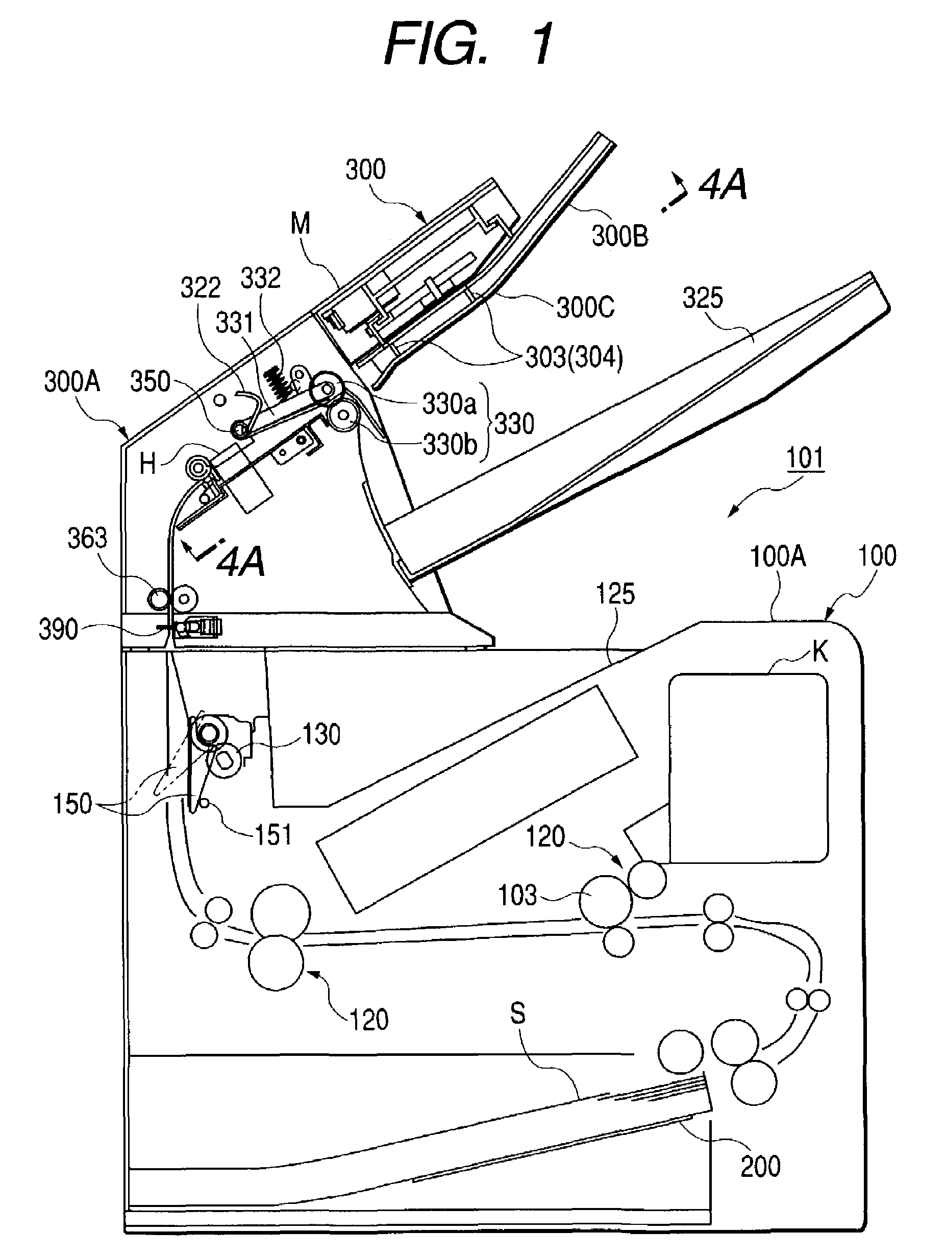
[0069]FIG. 1 is a schematic cross-sectional view showing the general construction of the printer 101 provided with the sheet post-treating apparatus 300 according,to the first embodiment of the present invention.

[0070]In FIG. 1, the printer 101 is an apparatus having a main body 100 singly connected to a computer or to a network such as LAN and for forming (printing) an image on a sheet by a predetermined image forming process on the basis of image information, a print signal or the like sent from the computer or the network, and discharging the sheet. This printer 101 may be provided with a reading portion for reading an original, and may be designed to copy the image of the original on the sheet on the basis of the read information by the reading portion and discharge the she...

second embodiment

(Second Embodiment)

[0144]A sheet post-treating apparatus 370 according to a second embodiment of the present invention will hereinafter be described with reference to FIGS. 15 to 19. In this embodiment, the same portions as those of the sheet post-treating apparatus 300 according to the first embodiment are given the same reference characters and need not be described.

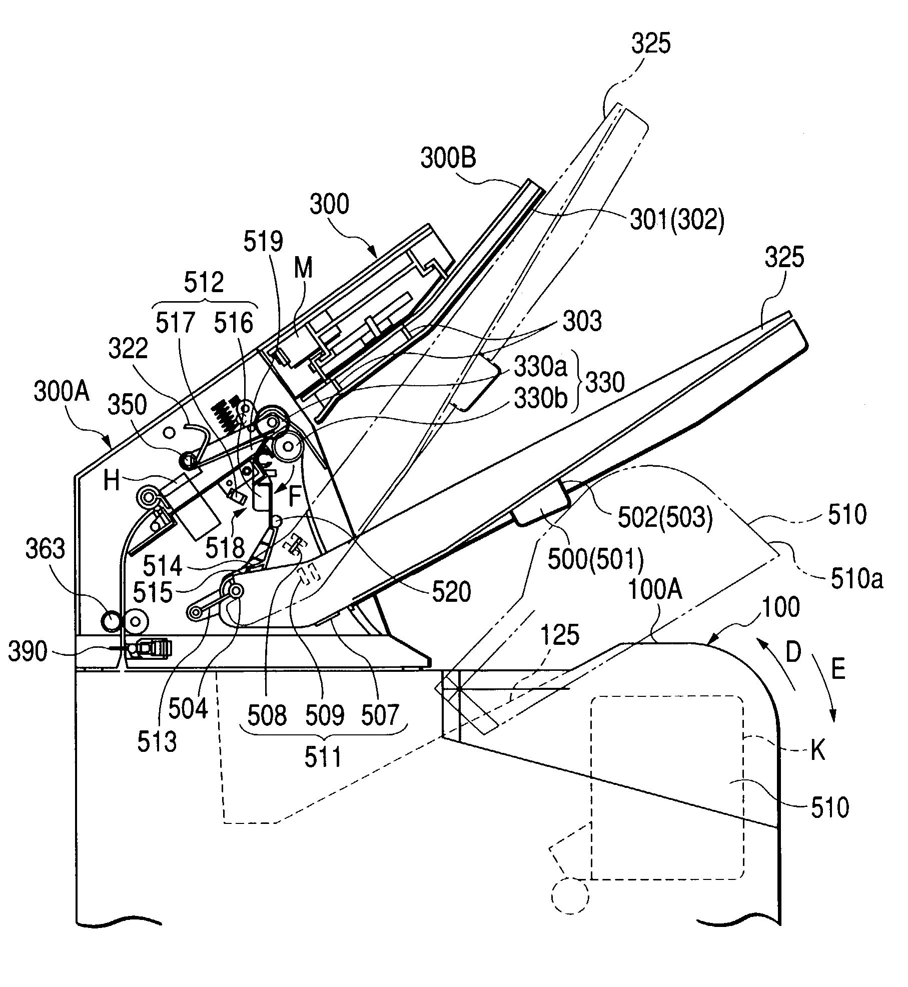
[0145]The sheet post-treating apparatus 370 according to the second embodiment is designed such that by the utilization of the construction of a full load detecting portion 530 for detecting that the discharged sheet stacking tray 325 is fully loaded with sheets, it is detected by a position detecting portion 529 that the discharged sheet stacking tray 325 is in the second position.

[0146]As shown in FIG. 15, the full load detecting portion 530 is comprised of a full load detecting flag 521, a photosensor 524, etc. The full load detecting flag 521 is adapted to be pivotally moved about a fulcrum 522 along the sheet stac...

third embodiment

(Third Embodiment)

[0154]A sheet post-treating apparatus 380 according to a third embodiment of the present invention will hereinafter be described with reference to FIGS. 20, 21, 22A and 22B. In this embodiment, the same portions as those of the sheet post-treating apparatus 300 according to the first embodiment are given the same reference characters and need not be described. Also, the operation of the discharged sheet stacking tray 325 being pushed up by the cartridge cover 510 is substantially the same as the operations of the sheet post-treating apparatus 300 according to the first embodiment and the sheet post-treating apparatus 370 according to the second embodiment and therefore need not be described.

[0155]The sheet post-treating apparatus 380 according to the third embodiment is provided with a holding portion 566 for automatically releasing the discharged sheet stacking tray 325 held in the second position when the user closes the cartridge cover 510.

[0156]The holding port...


PUM


Abstract

A sheet post-treating apparatus is provided with a discharged sheet stacking tray displaceably provided in a casing portion for stacking thereon sheets discharged from the casing portion, and a holding portion for holding the discharged sheet stacking tray in a first position and a second position overlying the first position, and is designed such that the sheets are stacked on the discharged sheet stacking tray when in the first position, and therefore, when the sheet post-treating apparatus is incorporated into a printer and a cartridge in the printer is to be interchanged with a cartridge cover opened, a user can retract the discharged sheet stacking tray to the second position to thereby interchange the cartridge.

Description

BACKGROUND OF THE INVENTION[0001]1. Field of the Invention[0002]This invention relates to a discharged sheet stacking apparatus on which sheets are stacked, and an image forming apparatus provided with this discharged sheet stacking apparatus in an image forming apparatus main body. Particularly, the invention relates to an image forming apparatus provided with a discharged sheet stacking apparatus designed such that when an ambient member is moved, a discharged sheet stacking tray does not abut against the member in an image forming apparatus.[0003]2. Related Background Art[0004]Heretofore, many image forming apparatuses, such as copying machines, printers, facsimile apparatuses and those combination machines thereof, have been designed such that sheets on which images have been formed (printed) are stacked on a discharged sheet stacking apparatus provided downstream of the discharge port of the image forming apparatus.[0005]Among such image forming apparatuses, there is one of a t...

Claims


Application Information

Patent Timeline
Patent Type & Authority Patents(United States)
IPC IPC(8): B65H31/00
CPCB65H31/00B65H2402/441B65H2511/152B65H2511/20B65H2511/51B65H2511/528B65H2601/324B65H2801/06B65H2801/27B65H2220/01B65H2511/15
Inventor SEKIYAMA, JUNICHIHAYAKAWA, YASUYOSHIKUWATA, TAKASHIOGATA, ATSUSHIISOBE, KENICHIROFUKATSU, MASAYOSHIATA, HIRONOBU
Owner CANON KK
Why Eureka
Try Eureka