
Multi-air conditioner and operation method thereof

a multi-air conditioner and air conditioning technology, applied in space heating and ventilation control systems, lighting and heating apparatus, heating types, etc., can solve the problems of conventional air conditioners not meeting the requirements of multi-operations, conventional air conditioners have limitations in meeting such requirements, and conventional air conditioners cannot meet selective air-conditioning requirements. to achieve the effect of improving air-conditioning efficiency

Inactive Publication Date: 2005-12-13
LG ELECTRONICS INC
View PDF22 Cites 10 Cited by
  • Summary
  • Abstract
  • Description
  • Claims
  • Application Information

AI Technical Summary

Benefits of technology

[0013]A further another object of the present invention is to provide a multi-air conditioner and an operation method thereof, in which in case a plurality of indoor units all operate in a cooling mode or in case a majority of indoor units operate in the cooling mode while the rest of them operates in a heating mode, a mixed ratio of refrigerant introduced into a distributor is controlled to improve the air conditioning efficiency.

Problems solved by technology

However, the conventional multi-air conditioner has a drawback in that even when some rooms among the partitioned rooms need to be heated while other rooms need to be cooled, since all the indoor units are operated in heating mode or cooling mode, the conventional multi-air conditioner does not meet the request of the aforementioned multi-operations.
However, the conventional air conditioners have a limitation in meeting such requirements.
However, the conventional air conditioner does not yet meet such selective air-conditioning requirements.

Method used


Image

  • Multi-air conditioner and operation method thereof
  • Multi-air conditioner and operation method thereof
  • Multi-air conditioner and operation method thereof

Examples


Embodiment Construction

[0042]Reference will now be made in detail to the preferred embodiments of the present invention, examples of which are illustrated in the accompanying drawings. Wherever possible, the same reference numbers will be used throughout the drawings to refer to the same or like parts.

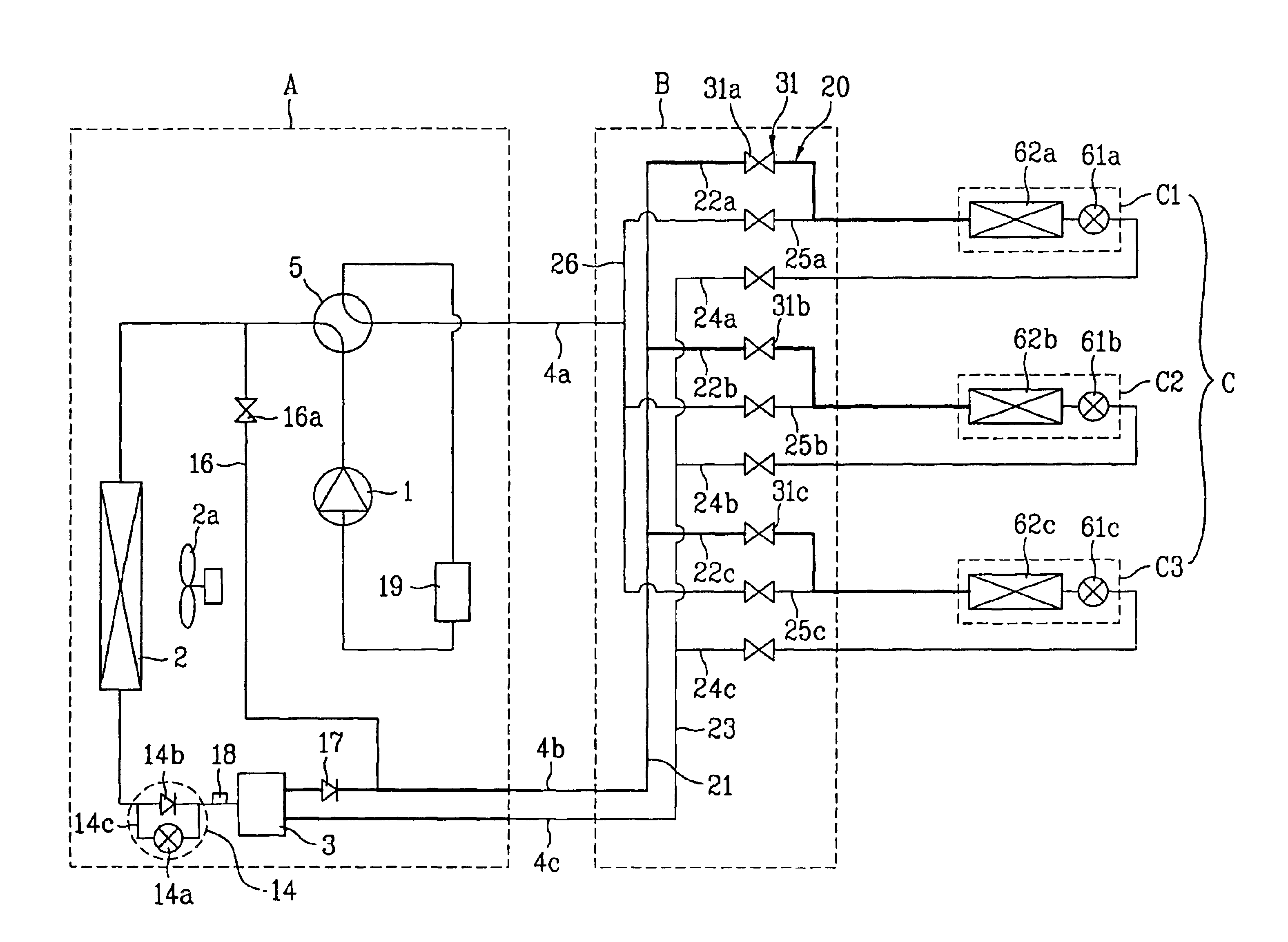
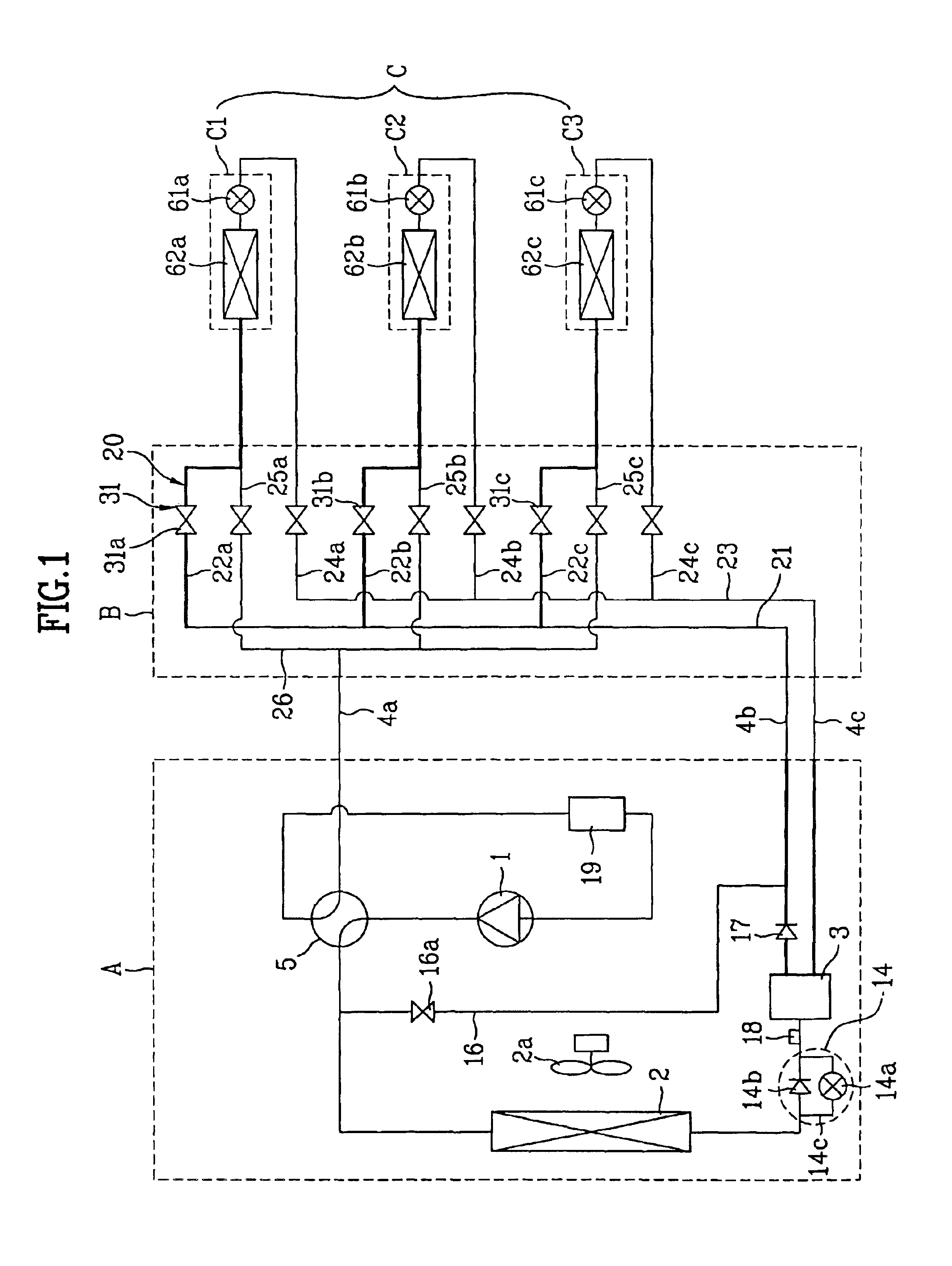
[0043]FIG. 1 is a construction view of illustrating structural elements of a multi-air conditioner according to a preferred embodiment of the present invention.

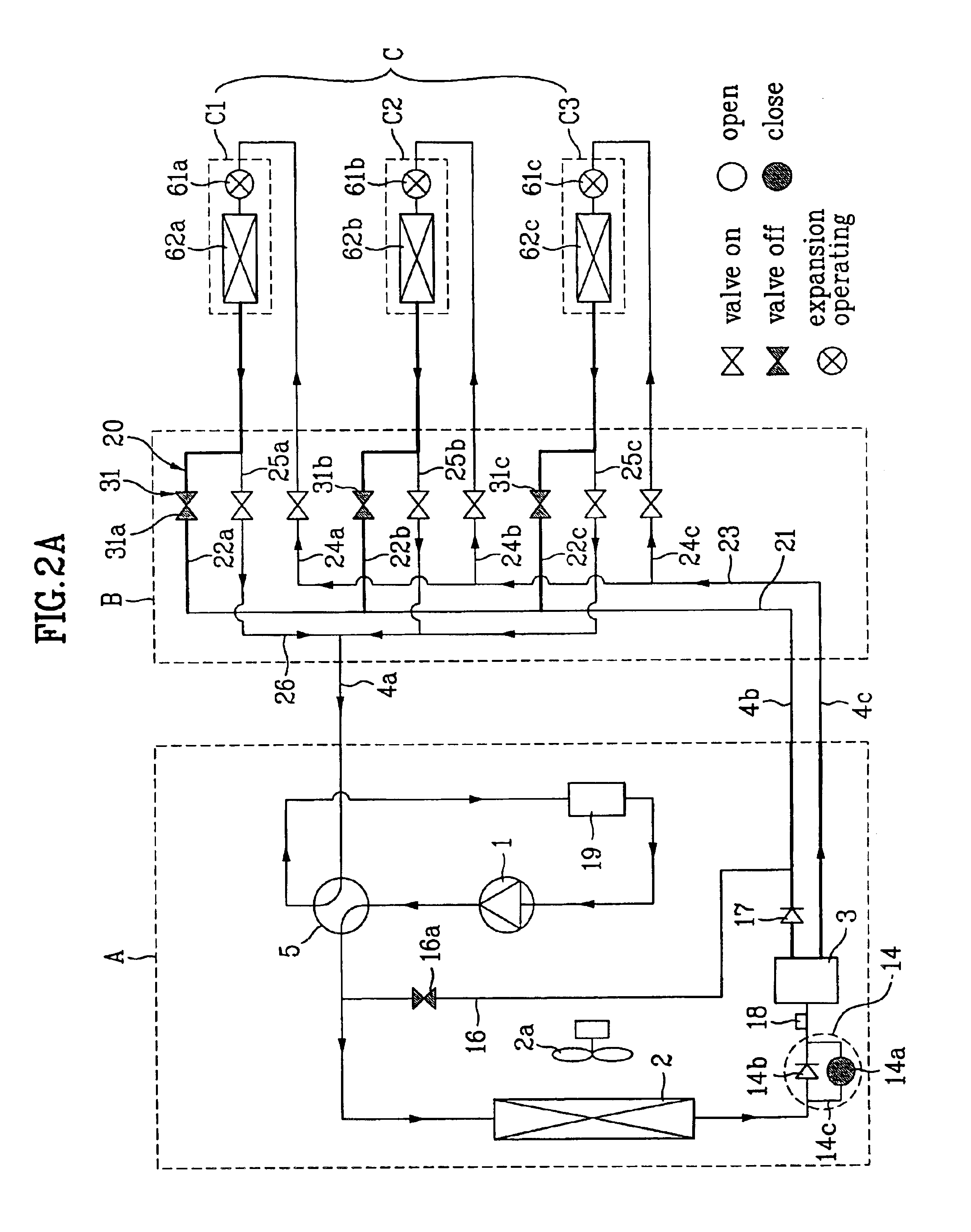
[0044]Herein, it is noted that a reference numeral 22 indicates “22a, 22b and 22c”, 24 indicates “24a, 24b and 24c”, 25 indicates “25a, 25b and 25c”, 31 indicates “31a, 31b and 31c”, 61 indicates “61a, 61b and 61c”, and 62 indicates “62a, 62b and 62c”, for description convenience. However, it will be understood that the numbers of the reference numerals can be changed depending on the numbers of indoor units.

[0045]As shown in FIG. 1, a multi-air conditioner includes an outdoor unit (A), a distributor (B), and a plurality of indoor units (C1, C2 and C3...


PUM


Abstract

Disclosed is a multi-air conditioner including: an outdoor unit having a compressor, an outdoor heat exchanger, and an outdoor fan for ventilating the outdoor heat exchanger; a plurality of indoor units each having an electronic expansion valve and an indoor heat exchanger; a distributor for selectively guiding a refrigerant of the outdoor unit into the plurality of indoor units according to an operation condition; a four-way valve for selectively switching a flow direction of the refrigerant flowing through the outdoor heat exchanger; a selective expansion unit for selectively expanding the refrigerant according to the flow direction of the refrigerant; a gas-liquid separator for separating a vapor-phase refrigerant and a liquid-phase refrigerant, from the refrigerant flowing from the outdoor heat exchanger; and a connection tube part having a first connection tube for connecting the four-way valve with a distributor, a second connection tube for connecting an upper portion of the gas-liquid separator with the distributor thereby guiding a vapor-phase refrigerant, and a third connection tube for connecting a lower portion of the gas-liquid separator with the distributor thereby guiding a liquid-phase refrigerant.

Description

[0001]This application claims the benefit of the Korean Application No. P2002-0049752 filed on Aug. 22, 2002, which is hereby incorporated by reference.BACKGROUND OF THE INVENTION[0002]1. Field of the Invention[0003]The present invention relates to a multi-air conditioner, and more particularly, to a multi-air conditioner and an operation method thereof capable of simultaneously performing cooling and heating operation.[0004]2. Discussion of the Related Art[0005]Generally, an air conditioner is an apparatus for cooling or heating an indoor space such as a residential space, office, restaurant and the like. Recently, a multi-air conditioner has been developed so as to more effectively cool or heat an inner space partitioned into a plurality of rooms.[0006]The multi-air conditioner is comprised of one outdoor unit, and a plurality of indoor units each being connected to the outdoor unit and being installed every room. The multi-air conditioner operates in one of heating mode and cooli...

Claims


Application Information

Patent Timeline
Patent Type & Authority Patents(United States)
IPC IPC(8): F25B13/00F25B29/00F25B41/04F24F11/02
CPCF25B13/00F25B2313/007F25B2313/0231F25B2313/0315F25B2400/23
Inventor PARK, JONG HANPARK, YOUNG MINLEE, CHANG SEONCHOI, SUNG OHKIM, SUNG CHUN
Owner LG ELECTRONICS INC
Learn More