Clamping or expanding pliers

Inactive Publication Date: 2005-12-13
WOLFCRAFT
View PDF7 Cites 29 Cited by
  • Summary
  • Abstract
  • Description
  • Claims
  • Application Information

AI Technical Summary

Benefits of technology

[0005]This advantage can be achieved, in the case of clamping or expanding pliers having the features of claim 1, by a spring element which is disposed in the region of action between the clamping section and handle section such that, with the two clamping sections secured in a spaced-apart position in relation to one another, the two handle sections can be displaced toward one another into another latching position in order to increase the clamping force.

Problems solved by technology

This results in effective expansion limiting.

Method used


Image

  • Clamping or expanding pliers
  • Clamping or expanding pliers
  • Clamping or expanding pliers

Examples


Embodiment Construction

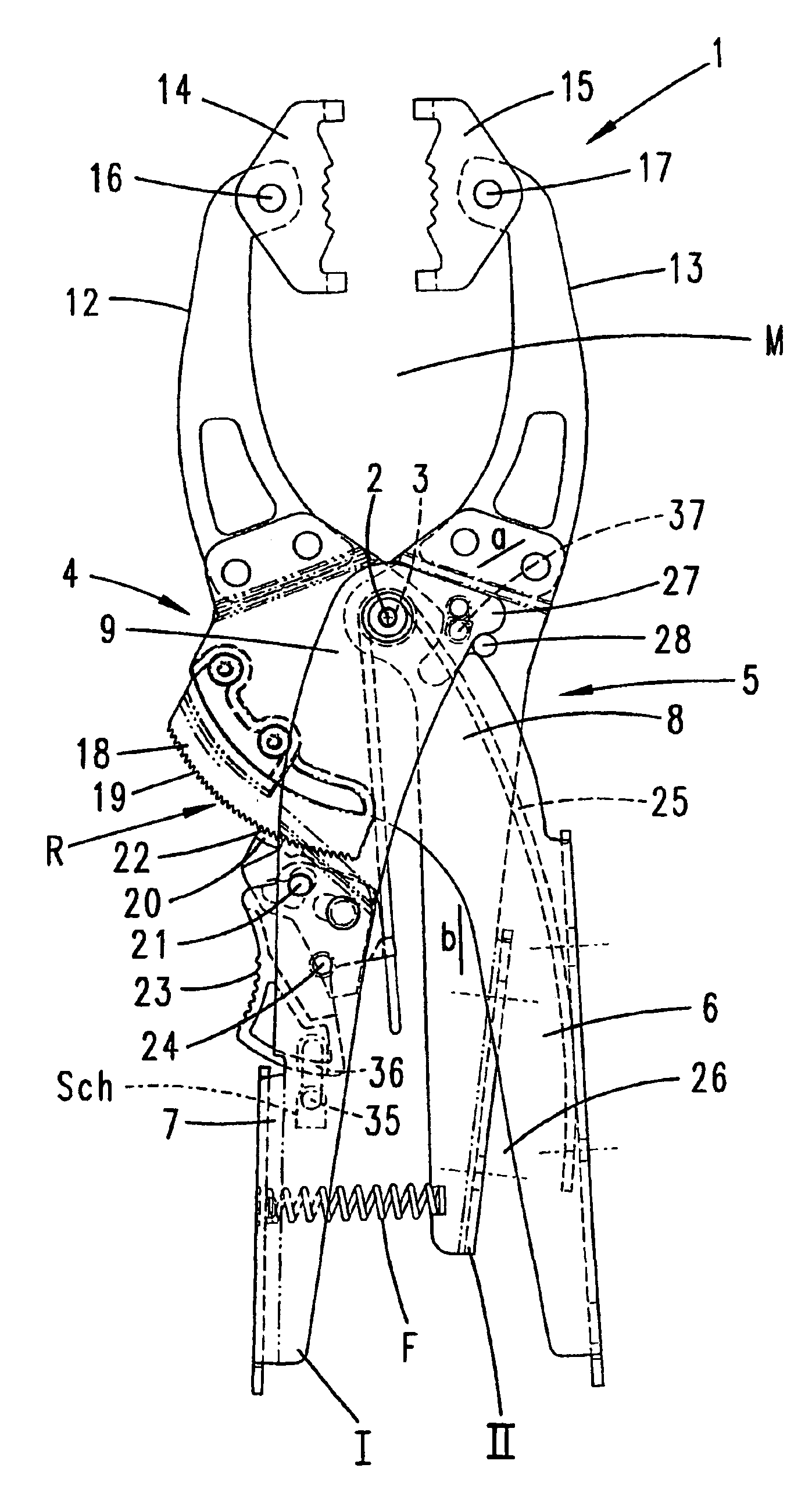
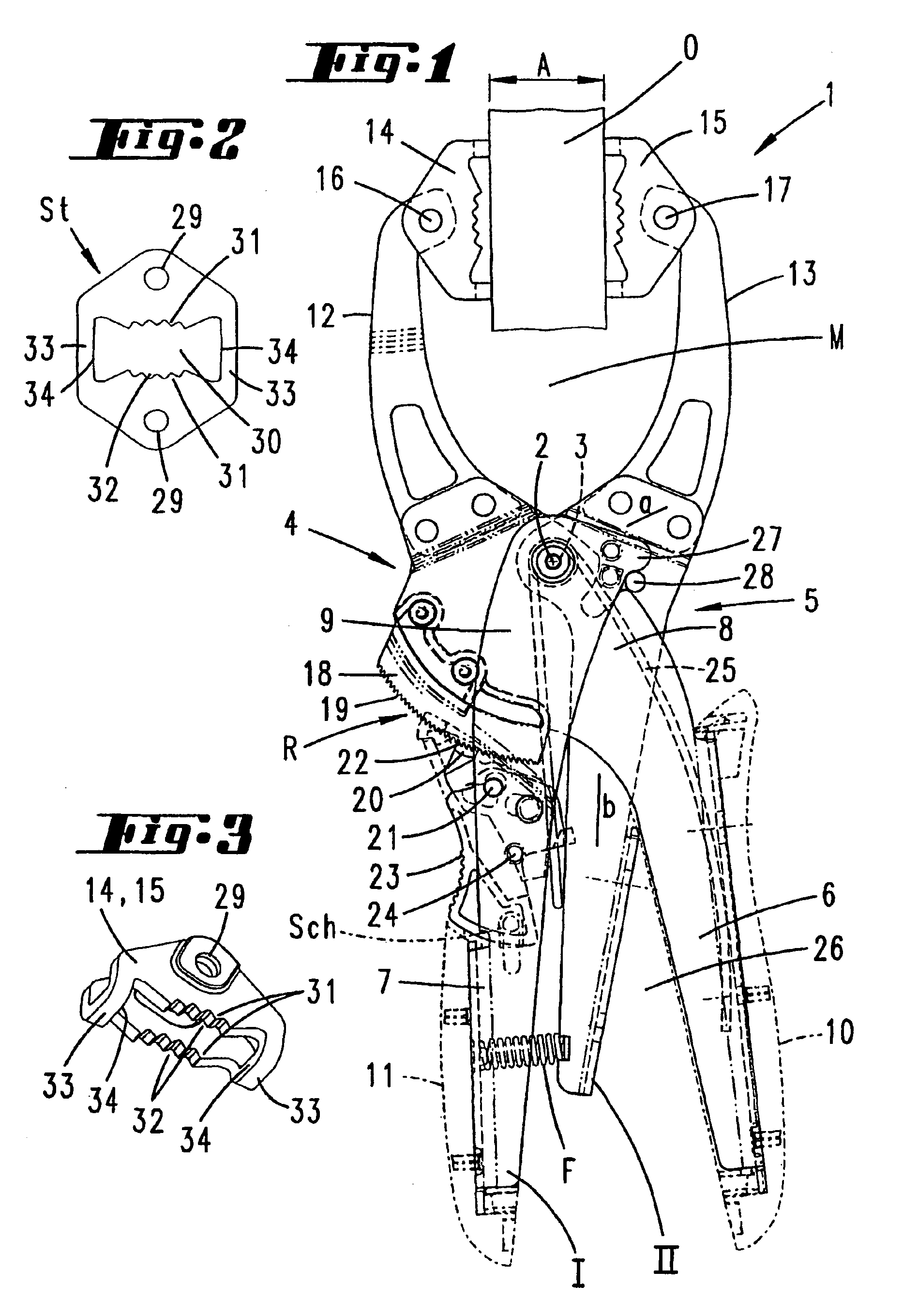
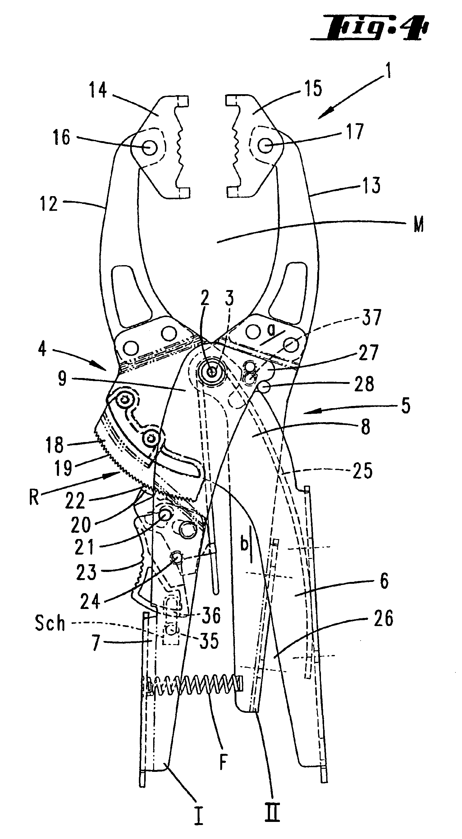
[0013]The clamping pliers 1 illustrated is constructed in the manner of a scissors joint, although a so-called through-joint is formed here.

[0014]The joint is formed by a pin, which will be referred to throughout as pliers joint 2.

[0015]The pin of the pliers joint 2 passes through congruent eyelets 3 in the crossover region of two pliers arms 4, 5. The latter comprise flexurally rigid profile bodies made of metal. Profile bodies in the stricter sense here are those regions of the pliers arms 4, 5 which are remote from the pliers joint, and form handle sections 6, 7. These take up a good two thirds to a half of the length of the pliers arms 4, 5. The plier arm 5 exhibits the longer profiling.

[0016]The profiling is formed by U-shaped parts, as seen in cross section. The U-openings of the handle sections 6, 7, which diverge in the direction away from the pliers joint, are directed toward one another and are in the same plane, in relation to the pivoting plane of the pliers arms 5, 6 of...


PUM


Abstract

Locking or expanding pliers (1) having two plier arms (4, 5) which arc joined to each other in the manner of a scissor-type joint. The arms forming grip sections (6, 7) on one end and clamping sections (12, 13) on the other end and being able to be locked in various clamping positions, whereby the clamping results from the elastic deformation of at least one of the two plier arms (4, 5) occurring when the plier arms (4, 5) are placed in a clamping position. A spring element (F) is arranged in the active area between the clamping section and the grip section in order to achieve improved proportioning of the clamping force, whereby both grip sections (6, 7) can be disposed on top of each other and placed in another locking position (19, 20), when both clamping sections (12, 13) are maintained in a distanced position (a), in order to increase clamping power.

Description

CROSS-REFERENCE TO RELATED APPLICATION[0001]This patent application claims priority of German patent application no. 10129130.2 filed Jun. 16, 2001 which is incorporated herein by reference.BACKGROUND OF THE INVENTION[0002]The invention relates to clamping or expanding pliers having two pliers arms which are connected to one another in the manner of a scissors joint, which form handle sections at one end and clamping sections at the other end and which can be latched in different clamping positions, the clamping force being the result of elastic deformation of at least one of the pliers arms, this deformation being associated with the movement of the pliers arms into the clamping position.[0003]Clamping or expanding pliers of this type are known from DE-A 199 33 033. For stress-relieving return deformation which eliminates the clamping action, the spring force, that is to say the restoring force of the pliers arms, is unblocked.SUMMARY OF THE INVENTION[0004]It can be an advantange o...

Claims


Application Information

Patent Timeline
IPC IPC(8): B25B7/02B25B7/12B25B7/14
CPCB25B7/02B25B7/12B25B7/14
Inventor NONIEWICZ, ZBIGNIEW
Owner WOLFCRAFT
Why Eureka
Try Eureka