Clutch piston assembly for increasing clamping force

Active Publication Date: 2019-09-03
WOLVERTON RONALD WAYNE +1
View PDF4 Cites 1 Cited by
  • Summary
  • Abstract
  • Description
  • Claims
  • Application Information

AI Technical Summary

Benefits of technology

The present invention is a clutch piston assembly that increasing clamping force without increasing hydraulic oil pressure. It can withstand the harsh heat environment within which it operates. The assembly is relatively simple in design and construction, being produced using standard manufacturing techniques that employ off the shelf parts, so it is cost-effective to produce. It does not require substantial torque converter or transmission modification. The technical effect of the invention is to provide a solution for increasing clamping force in a simple and efficient manner.

Problems solved by technology

As the RPMs increase, the clutches tend to slip against their reaction plates or steels which results in loss of power transfer from the engine to the drive wheels.
As even the small percentage power loss can be the difference between winning and losing a race, such a situation is highly undesirable.
While often effective, this technique increases the oil pressure within the transmission and torque converter, thereby increasing the oil's temperature and thus the internal operating temperature within the transmission and torque converter.
This increase in temperature results in premature oil break down, premature operating parts wear, and eventually system failure.
Another solution is to change the type of friction material used on the clutches and reaction plates but this can be either costly or simply may not be possible due to licensing and exclusivity agreements.

Method used


Image

  • Clutch piston assembly for increasing clamping force
  • Clutch piston assembly for increasing clamping force
  • Clutch piston assembly for increasing clamping force

Examples


Embodiment Construction

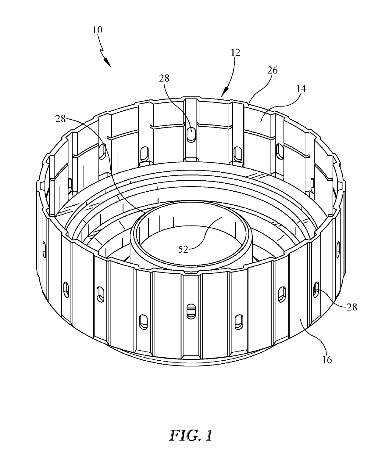
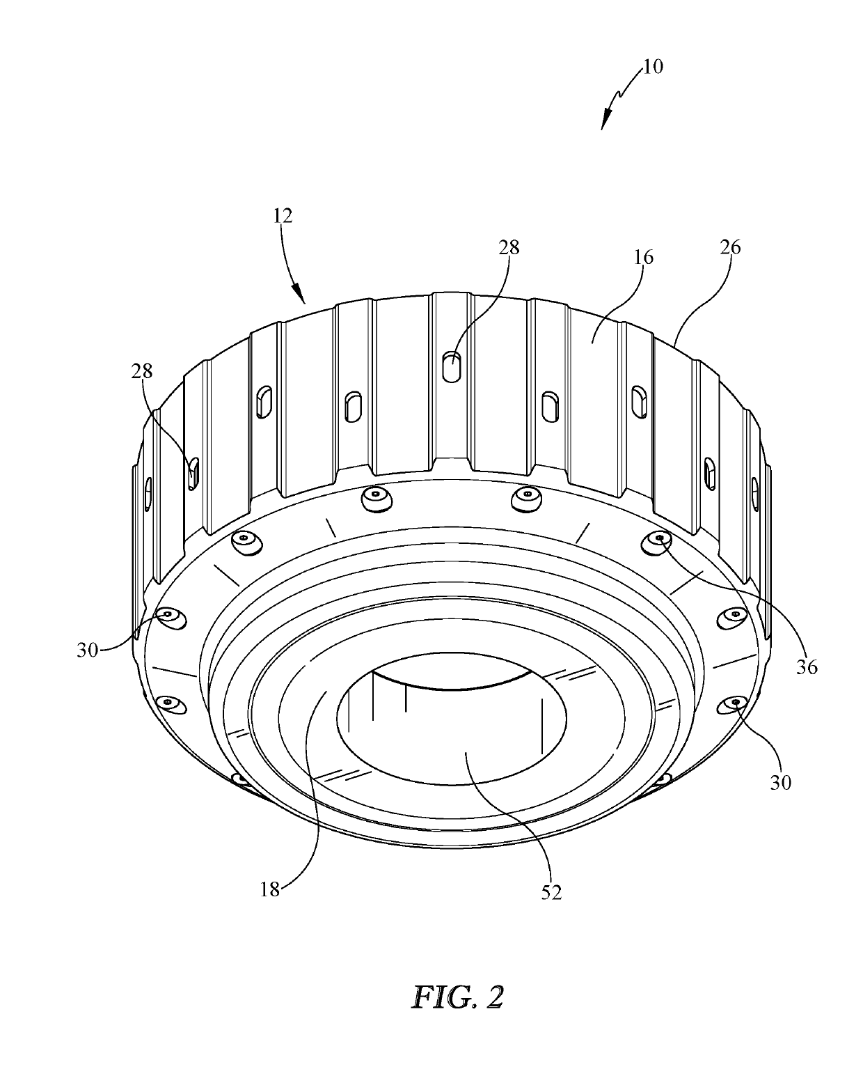
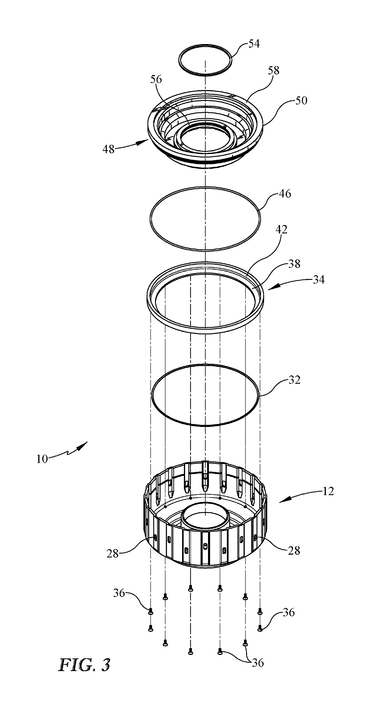
[0013]Referring now to the drawings, it is seen that the clutch piston assembly for increasing clamping force of the present invention, generally denoted by reference numeral 10, is comprised of a piston housing 12. As seen, the piston housing 12 has an interior wall surface 14 and an exterior wall surface 16. The piston housing 12 has a base 18 from which a central housing bore 20 rises upwardly. As seen, the base 18 transitions into an upwardly directed step 22 which transitions into a diagonally upwardly and outwardly directed shoulder 24, which transitions into an upwardly directed side wall 26. The piston housing 12 is formed as a single unitary, indeed monolithic, unit that can be formed from any appropriate material such as aluminum, steel, titanium, etc. A series of oil openings 28 are located along the side wall 26. The upwardly directed step 22 has a first diameter 30.

[0014]A first O-ring 32, made of any appropriate sealing material, such as silicone, rubber, neoprene, and...


PUM


Abstract

A clutch piston assembly increases the clamping pressure within a transmission or torque converter, without increasing the oil pressure, in order to reduce the slippage of the clutches against the reaction plates and has a piston housing that receives a cylinder bore ring atop of which is seated a cylinder bore. The cylinder bore has a series of progressively wider inner grooves with the uppermost groove being the widest yet substantially narrower than either of the cylinder bore ring's grooves, thereby decreasing the overall apply area of the central bore thereby increasing the clamping pressure that can be exerted by the clutch piston assembly.

Description

BACKGROUND OF THE INVENTION1. Field of the Invention[0001]The present invention relates to a clutch piston assembly within a transmission or torque converter that uses a separate piston cylinder bore and a replacement clutch piston that applies against reactions surfaces within the torque converter or transmission in order to increase clamping force on the clutches in order to reduce clutch slippage against their reaction plates without increasing the oil pressure within the system.2. Background of the Prior Art[0002]Racing vehicles operate at very high RPMs (Revolutions Per Minute). As the RPMs increase, the clutches tend to slip against their reaction plates or steels which results in loss of power transfer from the engine to the drive wheels. As even the small percentage power loss can be the difference between winning and losing a race, such a situation is highly undesirable. To address this problem, many designers increase the hydraulic pressure within the transmission or torqu...

Claims


Application Information

Patent Timeline
IPC IPC(8): F16D25/12F16D25/06F16H45/02
CPCF16D25/06F16D25/12F16H45/02F16D25/0638
Inventor WOLVERTON, RONALD WAYNEPOSADAS, CHRISTOPHER BRADLY
Owner WOLVERTON RONALD WAYNE
Why Eureka
Try Eureka