Compensating gripper with independent gripper adjustment
- Summary
- Abstract
- Description
- Claims
- Application Information
AI Technical Summary
Benefits of technology
Problems solved by technology
Method used
Image
Examples
Embodiment Construction
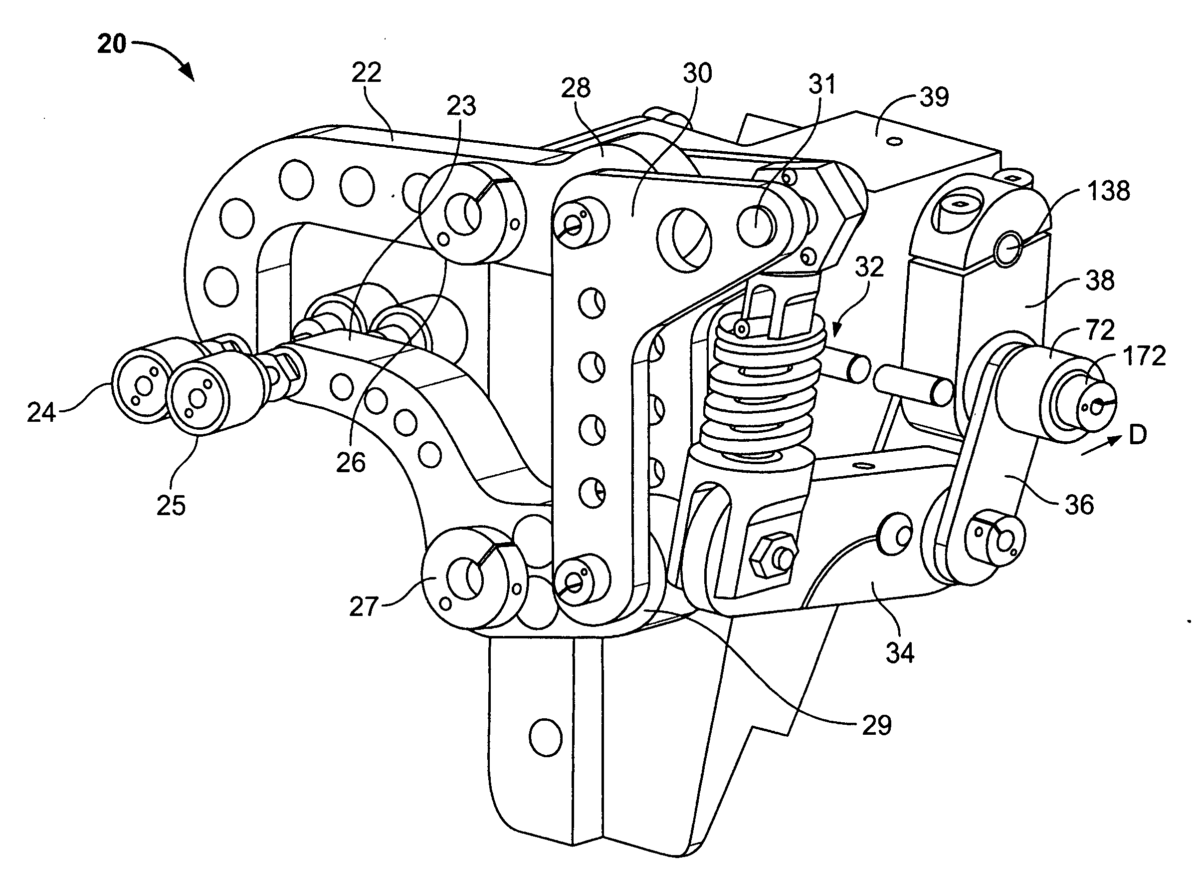
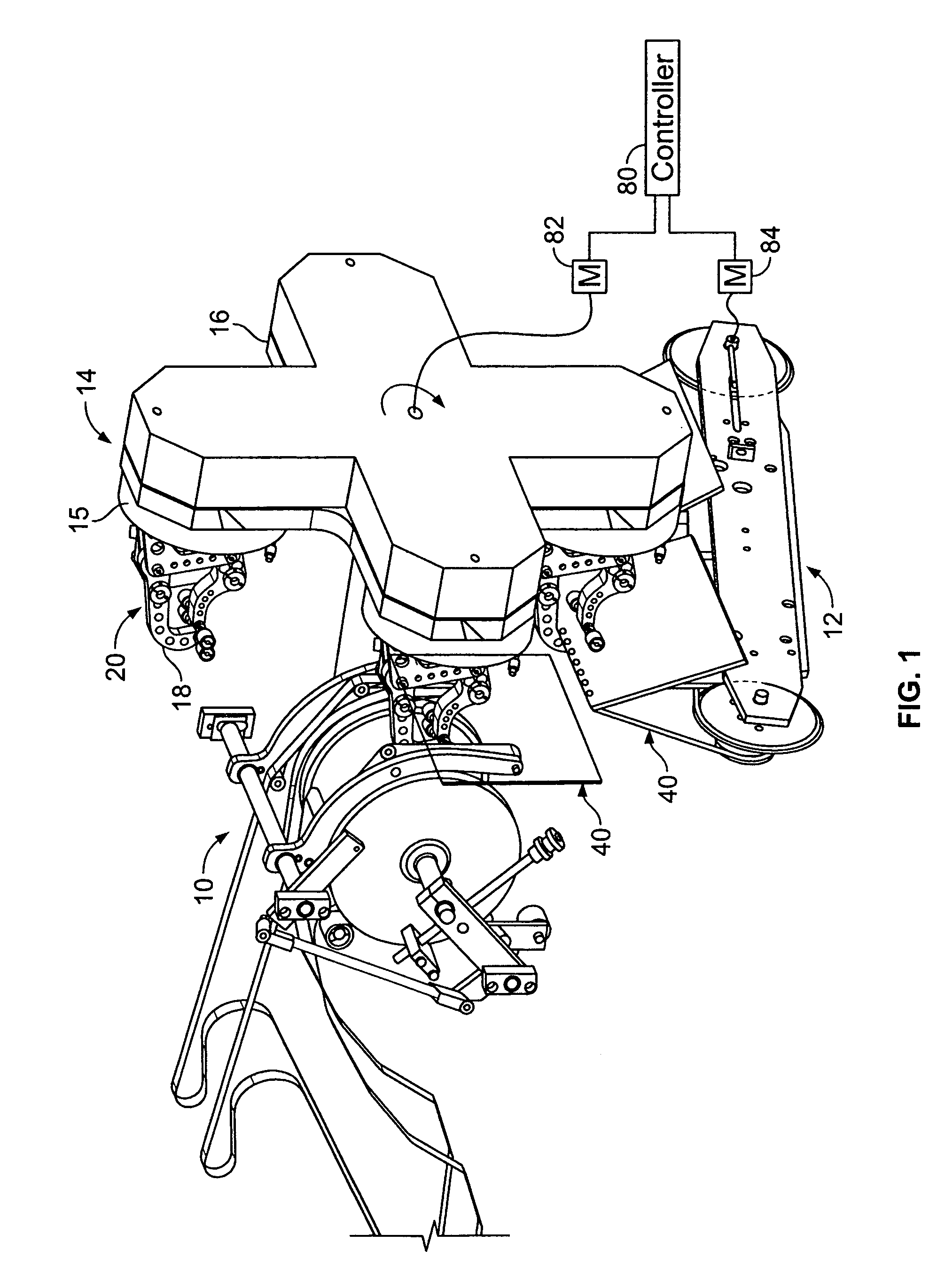
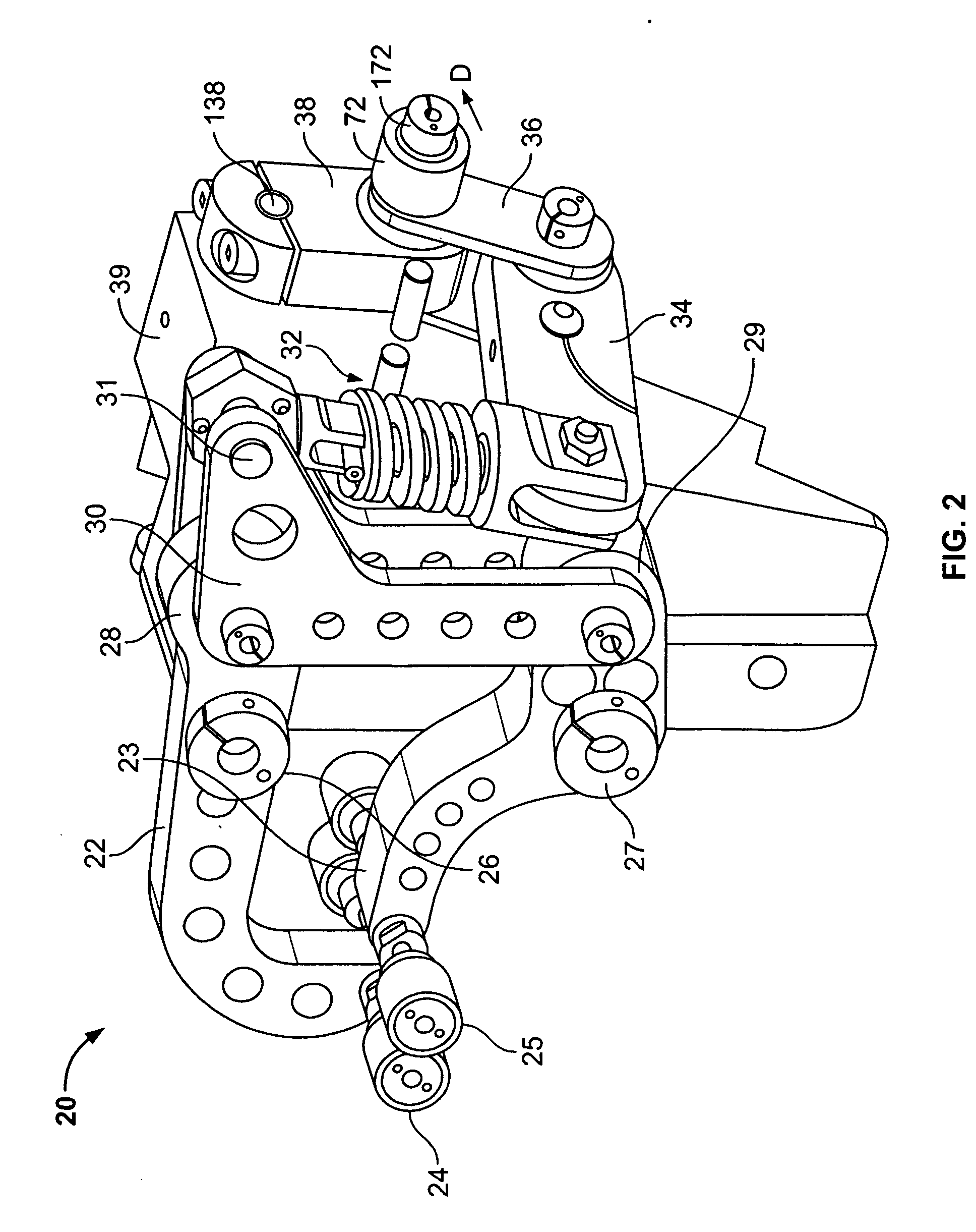
[0020]FIG. 1 shows a preferred embodiment of a gripping device 14 having gripper arms 16 with gripper bases 15. A gripper 20 is mounted on each base 15 in such a way to allow grippers 20 to rotate as gripper device 14 rotates. Thus, grippers 20 maintain an upright position 18 as gripper device 14 rotates clockwise.
[0021]As a printed product 40 is transported along an escalator tucker 12, escalator tucker 12 lifts printed product 40 up to be gripped by grippers 20. Gripper device 14 is timed with escalator tucker 12 via a controller 80 controlling individually driven servo motors 82, 84, although the escalator tucker 12 could be geared to gripping device 14 as well. Gripper 20 removes printed product 40 from escalator tucker 12 and delivers printed product 40 to delivery conveyor 10. Delivery conveyor 10 transports printed product 40 further along. Escalator tucker 12 may be similar to the signature transport device disclosed in U.S. Patent Application Publication No. 2005 / 0225023, h...
PUM
| Property | Measurement | Unit |
|---|---|---|
| Thickness | aaaaa | aaaaa |
| Electrical resistance | aaaaa | aaaaa |
Abstract
Description
Claims
Application Information
 - R&D
- Intellectual Property
- Life Sciences
- Materials
- Tech Scout
- Unparalleled Data Quality
- Higher Quality Content
- 60% Fewer Hallucinations
Browse by: Latest US Patents, China's latest patents, Technical Efficacy Thesaurus, Application Domain, Technology Topic, Popular Technical Reports.
© 2025 PatSnap. All rights reserved.Legal|Privacy policy|Modern Slavery Act Transparency Statement|Sitemap|About US| Contact US: help@patsnap.com


