Clamp structure

Active Publication Date: 2012-08-23
WISTRON NEWEB
View PDF10 Cites 6 Cited by
  • Summary
  • Abstract
  • Description
  • Claims
  • Application Information

AI Technical Summary

Benefits of technology

[0006]According to the claimed invention, a clamp structure includes a clamping component for clamping a tube, and at least one bridging component disposed on a lateral surface of the clamping component. A pivoting portion is formed on the bridging component, and the bridging component pivots to an antenna module via the pivoting portion, so that the antenna module pivots relative to the clamping component along a radial plane of the clamping component. An aim of the adjusting mechanism is that the antenna module can pivot relative to the supporting tube via the clamp within great range, and can further pivot along the pivot hole on the bridging component within tiny range after the clamp is fixed on the supporting tube by a fixing component set.
[0007]According to the claimed invention, the clamp structure further includes a supporting component disposed on the lateral surface of the clamping component and contacting against the bridging component for preventing the bridging component from bending relative to the clamping component.
[0008]According to the claimed invention, the clamp structure further includes two planks respectively connecting to two edges of the clamping component, and a fixing component set passing through the two planks for closing the two planks so as to increase clamping force of the clamping component applied on the tube.

Problems solved by technology

However, this conventional clamp structure has drawbacks of huge volume and expensive cost.

Method used


Image

  • Clamp structure
  • Clamp structure
  • Clamp structure

Examples


Embodiment Construction

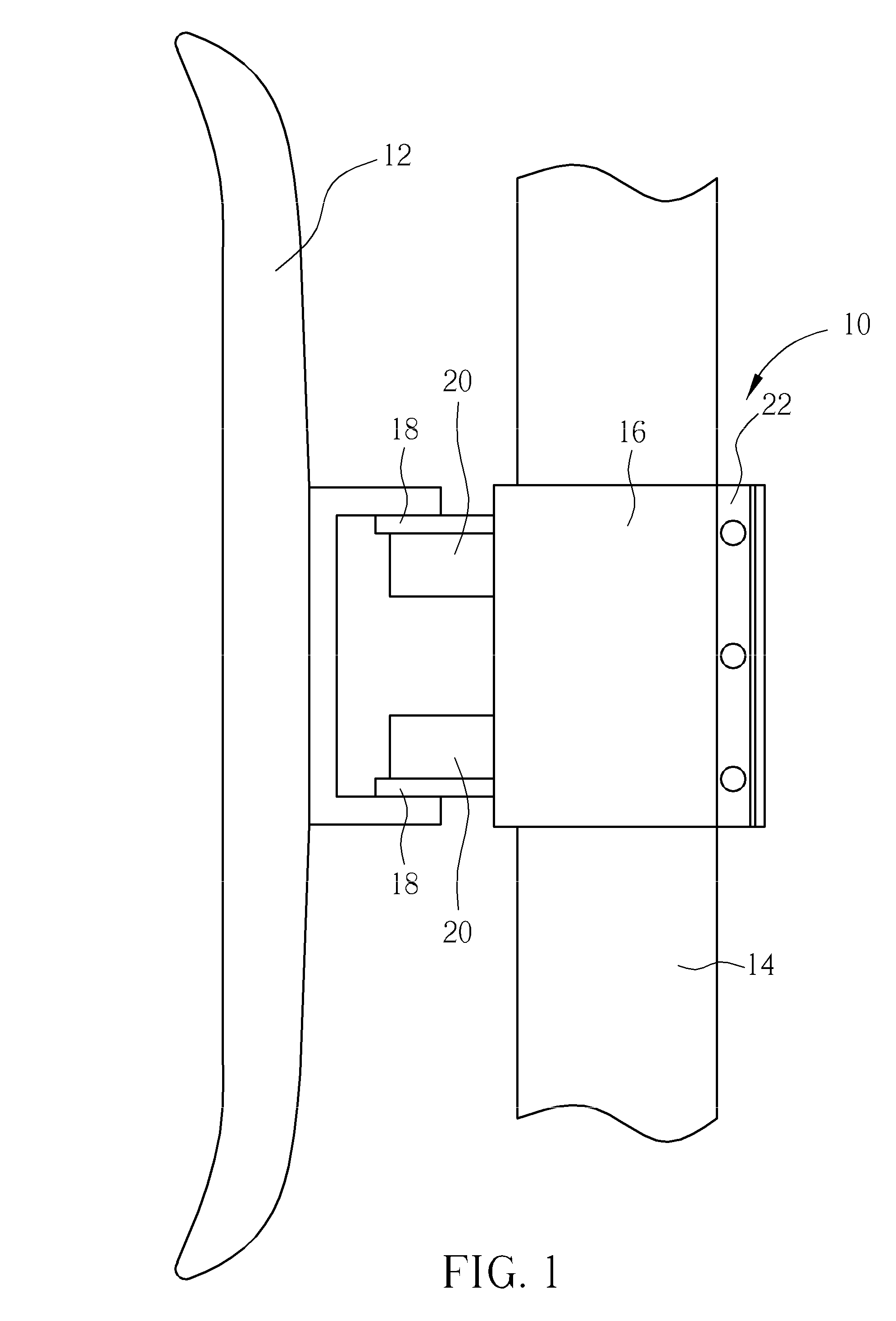
[0018]Please refer to FIG. 1. FIG. 1 is a diagram of a clamp structure 10 and corresponding components according to an embodiment of the present invention. The clamp structure 10 can pivot to an antenna module 12 and sheathe on a tube 14, so that an angle between the antenna module 12 and the tube 14 can be adjusted via the clamp structure 10.

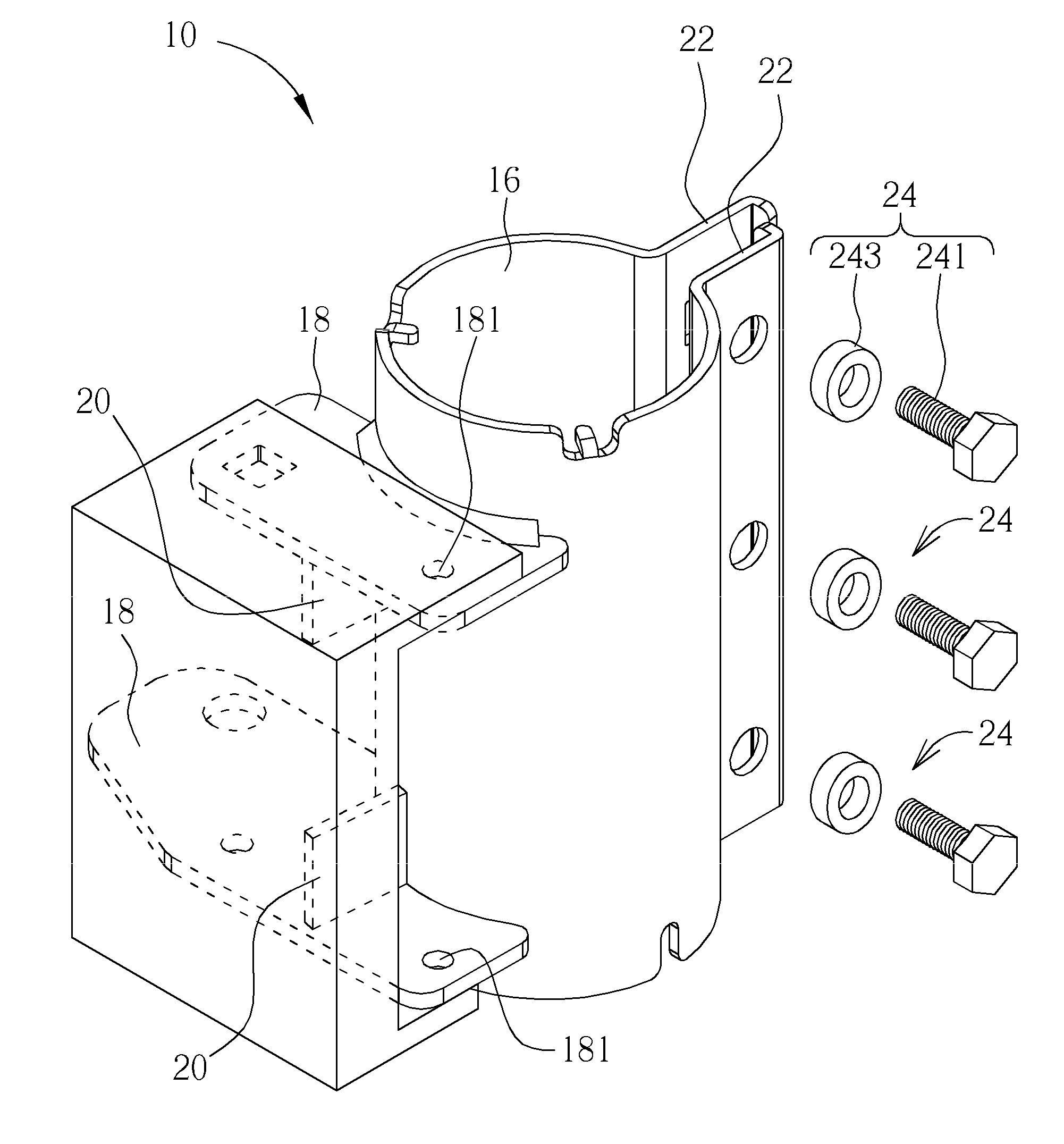
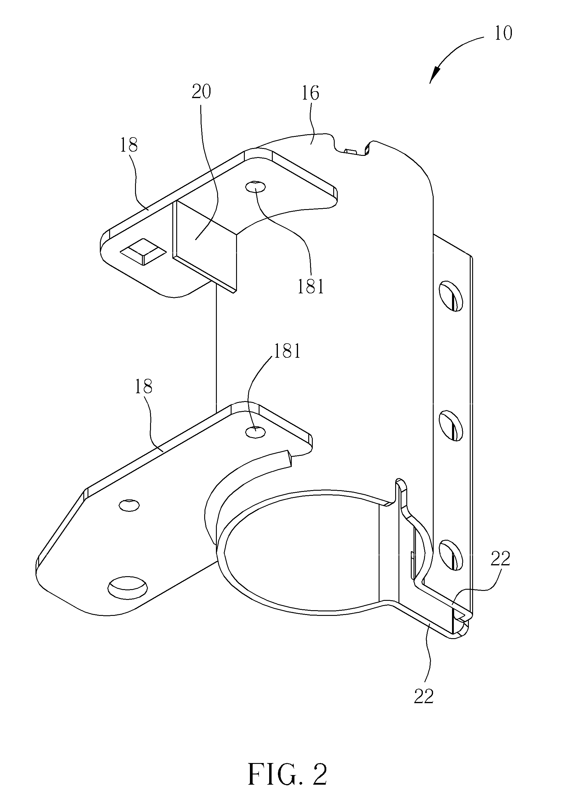
[0019]Please refer to FIG. 2 and FIG. 3. FIG. 2 and FIG. 3 are diagrams of the clamp structure 10 in different view angles according to the embodiment of the present invention. The clamp structure 10 includes a clamping component 16 for clamping the tube 14. The tube 14 can be an annular tube, and the clamping component 16 can be an annular structure correspondingly. The clamp structure 10 further includes at least one bridging component 18 connected to a lateral surface of the clamping component 16 by mechanical treatment, such as a soldering manner or an integrally-formed manner. The bridging component 18 can further stretch from the lateral ...


PUM


Abstract

A clamp structure is disclosed in the present invention. The clamp structure includes a clamping component for clamping a tube, and at least one bridging component disposed on a lateral surface of the clamping component. A pivoting portion is disposed on the bridging component, and the bridging component pivots with an antenna module via the pivoting portion, so that the antenna module can pivot relative to the clamping component along a radial plane of the clamping component.

Description

BACKGROUND OF THE INVENTION[0001]1. Field of the Invention[0002]The present invention relates to a clamp structure, and more particularly, to a clamp structure for bridging a platform.[0003]2. Description of the Prior Art[0004]For installing an antenna module on a tube, a conventional assembly is disposing the antenna module on a clamp structure, and locking the clamp structure on the tube. A conventional clamp structure includes an annular clamping component for clamping the annular tube, and a bridging component disposed on the annular clamping component. The antenna module is installed on the bridging component of the clamp structure. The conventional clamp structure connects the bridging component to the lateral surface of the annular clamping component as a planar direction of the bridging component is parallel to an axial direction of the annular clamping component. Therefore, the antenna module can pivot relative to the annular clamping component along a direction perpendicul...

Claims


Application Information

Patent Timeline
IPC IPC(8): H01Q1/12F16B2/10
CPCF16B2/08Y10T24/44017H01Q1/1228
Inventor LEE, MING-CHANYANG, LAN-CHUNLIN, HUNG-YUANKUO, SAN-YICHIEN, WEI-TE
Owner WISTRON NEWEB
Why Eureka
Try Eureka